In the "final mile" of casting processing, precision often determines product value. Whether it's sealing surfaces of engine blocks, mating holes in hydraulic valve blocks, or support surfaces of machine tool guideways, all require extremely high dimensional accuracy and surface finish to meet assembly and operational requirements. However, after casting and machining, castings often retain milling marks, dimensional deviations, and even micro-deformations, making traditional grinding methods (such as manual wheel polishing) inadequate for achieving precision standards. Metal precision grinding, with its characteristics of "micrometer-level accuracy control" and "uniform surface processing," has become the core process for achieving high precision and stability in castings. Today, we will explore how metal precision grinding adapts to casting processing needs and addresses the limitations of traditional methods through three dimensions: improving casting surface precision, correcting critical dimensions, and repairing defects.
Surface precision improvement of casting: from "rough blank" to "precision contact surface"
After casting and rough machining, castings often face two major surface issues: First, high surface roughness (Ra50-12.5μm) with visible milling marks or sand hole traces; second, poor flatness (such as planeness errors 0.1-0.5mm/m), making them unsuitable for precision assembly requirements like sealing and fitting. Metal precision grinding addresses these problems through various grinding processes, achieving a "refined upgrade" of casting surfaces.
1. Planar grinding: solve the "flatness problem" of casting sealing surface and support surface
For the planar structures of castings (such as the sealing surface of an engine cylinder head or the support surface of a machine tool base), planar grinding is the most commonly used process. It removes excess material from the surface 0.01-0.1mm through high-speed rotation of a grinding wheel (grit size 80-120 mesh) moving back and forth across the casting surface, controlling surface flatness errors within 0.005-0.02mm/m and reducing surface roughness to Ra0.8-0.2μm.
Consider a gray cast iron cylinder block (material HT250) manufactured by an automotive engine plant. After milling, the cylinder head sealing surface still exhibited a flatness error of 0.2mm/m. Direct assembly would have caused oil leakage. Through surface grinding (using resin-bonded abrasive wheels at 30m/s speed with 0.05mm feed per pass), the flatness error was reduced to within 0.01mm/m. This process also created uniform micro-textures on the sealing surface, enhancing gasket adhesion and reducing the leakage rate from 15% to below 0.5%.
It is worth noting that planar grinding requires adjustment of the type of grinding wheel according to the material of the casting: brittle materials such as gray cast iron and ductile cast iron are suitable for use of corundum grinding wheel (to avoid sand blockage); plastic materials such as stainless steel and aluminum alloy are required to use silicon carbide grinding wheel (to improve grinding efficiency and reduce chip adhesion).
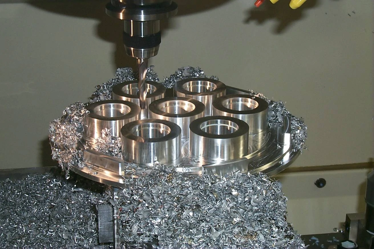
2. External circle grinding: optimize the "roundness and coaxiality" of cast shafts and cylindrical surfaces
Casting components such as shafts (e.g., drive shafts, hydraulic cylinder piston rods) and cylindrical structures (e.g., inner bore of bearing housings) require extremely high precision in roundness and coaxiality. —— If the roundness error exceeds 0.005mm, it may cause vibration and abnormal noises during operation; significant coaxiality deviations can compromise bearing assembly accuracy. External cylindrical grinding utilizes a compound motion of "wheels rotating around the workpiece + the workpiece's own rotation" to precisely correct these errors.
Taking a ductile iron drive shaft (50mm diameter, 300mm length) as an example, its lathe machining resulted in a roundness error of approximately 0.02mm and coaxiality deviation of 0.03mm. Through external cylindrical grinding (using CBN grinding wheels with 40m/s grinding speed and 0.005mm/revolution radial feed), the final roundness error was controlled within 0.002mm and coaxiality deviation ≤0.008mm, fully meeting the interference fit requirements between the bearing and shaft (clearance 0.003-0.008mm).
The key to external circular grinding is "center positioning" —— The center hole at both ends of the workpiece should be calibrated first to ensure that the rotation axis of the workpiece is parallel to the axis of the grinding wheel, so as to avoid the problem of "taper" (that is, the diameter of both ends of the workpiece is inconsistent) caused by positioning deviation.
3. Internal grinding: conquer the "precision bottleneck" of casting hole structur
Traditional milling and boring techniques often fail to achieve the required precision for internal casting components (e.g., hydraulic valve block oil passages or bearing housing mounting holes) due to limited machining space, frequently resulting in issues such as diameter deviations (±0.05mm) and rough surfaces (Ra6.3μm). Internal cylindrical grinding employs a "small-diameter grinding wheel insertion" method, capable of machining internal holes with diameters ranging from 5mm to 500mm and depths up to 1000mm. This technique achieves ±0.005mm dimensional tolerances while reducing surface roughness to Ra0.4-0.1μm.
Consider a stainless steel valve block (Grade 304) manufactured by an engineering machinery plant. The oil passage bore (20mm diameter, 80mm depth) showed a 0.04mm dimensional deviation after boring, with visible tool marks on the wall. Through internal cylindrical grinding using a 15mm ceramic-bonded abrasive wheel at 25m/s speed with 0.02mm/revolution feed, the process not only achieved precise dimensional correction to 20±0.003mm but also created a mirror-like smooth surface. This improvement reduced hydraulic fluid flow resistance and enhanced the valve block's oil control precision.
Correction of key dimensions of castings: use precision grinding to "recover" unqualified blanks and reduce losse
During the casting cooling process, castings are prone to dimensional deviations —— due to uneven shrinkage and mold deformation. For instance, a base casting designed for 1000mm length may develop an actual length 1000.5mm, while a flange plate intended for 20mm thickness might end up being 19.8mm. When such deviations exceed tolerance limits, traditional methods often result in scrap casting and material waste. However, precision metal grinding employs a "micro-elimination of allowance" technique to accurately correct dimensions. This method transforms defective blanks into qualified products, significantly reducing casting defect rates.
1. Linear size correction: millimeter deviation, micron adjustment
Precision grinding can effectively correct linear dimensional deviations such as length, width, and thickness in castings by controlling the "grinding allowance". For example, a machine tool factory processed a cast iron worktable (design dimensions: 2000mm × 1000mm × 30mm). Due to uneven cooling shrinkage, the actual thickness 29.7mm (deviation: -0.3mm) had a 0.1mm milling allowance on its surface. Through planar grinding (conducted in three stages, each removing 0.1mm of allowance), the final thickness was corrected to 30±0.01mm, fully meeting the design tolerance requirements (±0.02mm).
This "micro-abreast" grinding method not only avoids the thermal deformation of castings caused by excessive single-grinding amounts (grinding temperature usually ≤150℃, heat-affected zone ≤0.01mm) but also ensures the stability of dimensional correction ——. For a batch of 20 workpieces, the dimensional deviation can be controlled within ± 0.008mm, and the pass rate has increased from the original 60% to 98%.
2. Form and position tolerance correction: solve the assembly problem of "not straight, not round, not parallel
Beyond linear dimensions, form and position tolerances (such as straightness, parallelism, and perpendicularity) in castings significantly impact assembly ——. For example, a linear error exceeding 0.01mm/m in guide rail castings can cause machine tool sliders to run sluggishly, while excessive perpendicularity deviations in flange end faces may lead to poor sealing. Through "targeted process design," precision grinding can effectively correct these deviations.
Taking a guide rail casting (material HT300, length 3000mm) as an example, its straightness error after milling was 0.05mm/m with parallelism deviation of 0.03mm/m. Through the "Guide Rail Specialized Grinding Process" (using an extended grinding wheel for continuous longitudinal grinding along the guide rail while monitoring straightness in real-time via laser interferometry), the straightness error was reduced to 0.005mm/m and parallelism deviation ≤0.008mm/m, meeting the operational requirements of high-precision machine tools (with operational resistance fluctuation ≤5%).
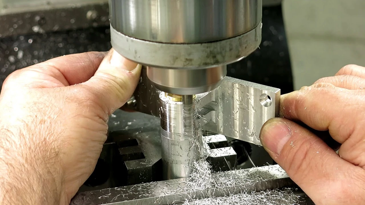
Cast part defect repair: use precision grinding to "repair" minor defects, avoid scrappin
During casting processing, minor defects may occur —— such as surface scratches (depth 0.02-0.05mm), localized protrusions (height 0.03-0.1mm), and uneven surfaces after sand filling (using cast iron welding rods). If left untreated, these defects can affect both the product's appearance and performance. However, discarding them outright would be wasteful. Metal precision grinding can address these issues through "local fine grinding," allowing castings to regain compliance with quality standards.
1. Surface scratch and bulge repair: accurately remove defects without damage to the substrat
The "local small-area grinding" technique —— uses a small grinding wheel (50-100mm diameter) to specifically target the defective area. This method removes 0.01-0.03mm surface material while eliminating scratches and protrusions, without affecting the dimensional accuracy or surface quality of surrounding areas.
For example, a medical device manufacturer encountered scratches measuring 5mm in length and 0.03mm in depth on its aluminum alloy castings (material grade 6061). Through localized grinding using fine-grit aluminum oxide wheels at 25m/s speed with 0.002mm feed per pass, the scratches were completely removed. The surface roughness of the repaired area matched the surrounding surfaces (both achieving Ra0.4μm), meeting aesthetic requirements without requiring additional polishing.
2. Smooth repair after sand filling: make the filling area "seamlessly connected" with the substrat
Microscopic porosities (diameter ≤2mm) within castings are typically filled using base metal distinct steps at the junction between the filled area and substrate. Through precision grinding techniques—initially rough grinding to remove excess material followed by finish grinding for surface refinement—the filled area can be aligned with the substrate surface. This process achieves flatness errors ≤0.005mm while eliminating visible marks at the joint interface.
For instance, a cast steel component (material ZG270-500) from a heavy industry manufacturer exhibited pinholes measuring 1.5mm in diameter. After filling, the surface protruded by 0.15mm. Through a process combining "rough grinding (using 60-grit abrasive with 0.12mm allowance) + precision grinding (120-grit abrasive with 0.03mm allowance)", the filled area achieved full alignment with the substrate. Ultrasonic testing confirmed that the combined strength matched the base material, fully meeting load-bearing requirements (tensile strength ≥500MPa).
Key points of matching between casting and metal precision grinding: material, defect and proces
Not all castings are suitable for precision grinding. It is necessary to select appropriate grinding process and parameters according to the material characteristics, surface defect types and precision requirements of castings, so as to avoid problems such as "low grinding efficiency", "surface burn" and "dimensional deviation".
1. Material adaptation: different grinding wheels and grinding parameters are selected according to different casting materials
- Cast iron (gray cast iron, ductile cast iron): brittle, easy to produce dust when grinding, suitable for use of corundum grinding wheel (brown corundum, white corundum), grinding speed 25-30m/s, feed 0.05-0.1mm/ times to avoid sanding wheel blockage;
- Stainless steel (304,316): strong plasticity, easy to stick, need to use silicon carbide grinding wheel or CBN grinding wheel, grinding with coolant (emulsion), reduce grinding temperature (controlled below 120℃), reduce sticking and surface burn;
Aluminum alloy (6061,7075): soft texture, easy to deform when grinding, suitable for fine grain alumina grinding wheel (particle size 120-180), low feed (0.02-0.05mm/ times), high grinding speed (35-40m/s), reduce thermal deformation.
2. Defect adaptation: Select local or overall grinding according to the type of defect
- Poor surface roughness, overall dimensional deviation: suitable for overall grinding (such as plane grinding, outer circle grinding), improve the precision of the whole surface at one time;
- Local scratch, bulge and sand filling: suitable for local small range of grinding, avoid excessive processing resulting in waste of size;
Form and position tolerance deviation (such as flatness, coaxiality): it is necessary to select special grinding process (such as guide rail grinding, inner circle grinding), and correct the error through accurate positioning and monitoring.
epilogue
In casting processing, metal precision grinding serves as both a "quality guardian" and "defect fixer" ——. It not only elevates castings from "rough semi-finished products" to "high-precision finished goods," but also mitigates scrap losses caused by dimensional deviations and minor defects, providing highly adaptable and stable solutions for casting manufacturing. For professionals in casting production, understanding the compatibility logic between precision grinding and castings enables better process planning. This approach ensures precision while reducing costs, ultimately enhancing product competitiveness.
If you have any questions about "the selection of grinding parameters for castings with different materials" and "the precision grinding scheme for castings with complex structures", please leave a comment in the comment section. We will continue to share more popular science knowledge related to casting and metal precision grinding!