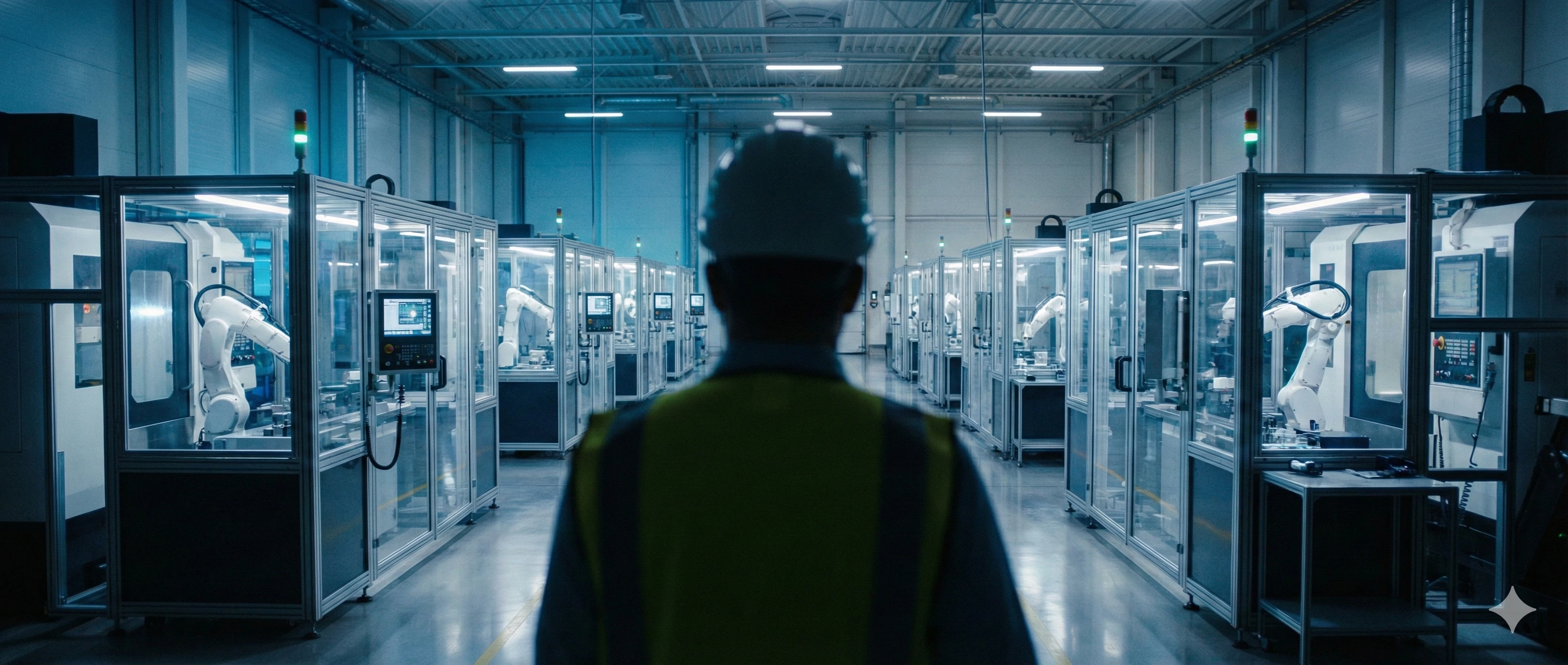
When we walk clients through our factory floor in Rizhao, they often marvel at the sound of metal being cut. But for our engineering team, that sound represents a critical balance between speed and perfection. We know that in the hardware industry, a difference of a few microns can turn a valuable shipment into scrap metal. It creates a massive headache for procurement managers who need parts that fit perfectly every single time. To avoid these costly errors, we rely on advanced technology that removes human guesswork from the equation.
CNC Precision Machining is a subtractive manufacturing process where computer-controlled tools remove material to create parts with extreme accuracy. Unlike standard machining, this method achieves microscopic tolerances of +/- 0.01mm or better, ensuring components meet exact specifications for fit, seal, and interchangeability in critical industrial applications.
In this guide, we will break down exactly how this technology works, the different types of machines we use, and why it is the perfect partner to our casting process.
How Does the CNC Process Work From Digital to Physical?
Our engineers frequently sit down with clients to explain how a digital drawing on a screen transforms into a solid stainless steel component. Many buyers worry that the design they approve might not match the final product they receive. This anxiety is understandable, especially when dealing with . At our facility, we follow a strict four-step workflow to ensure that the digital intent matches the physical reality perfectly.
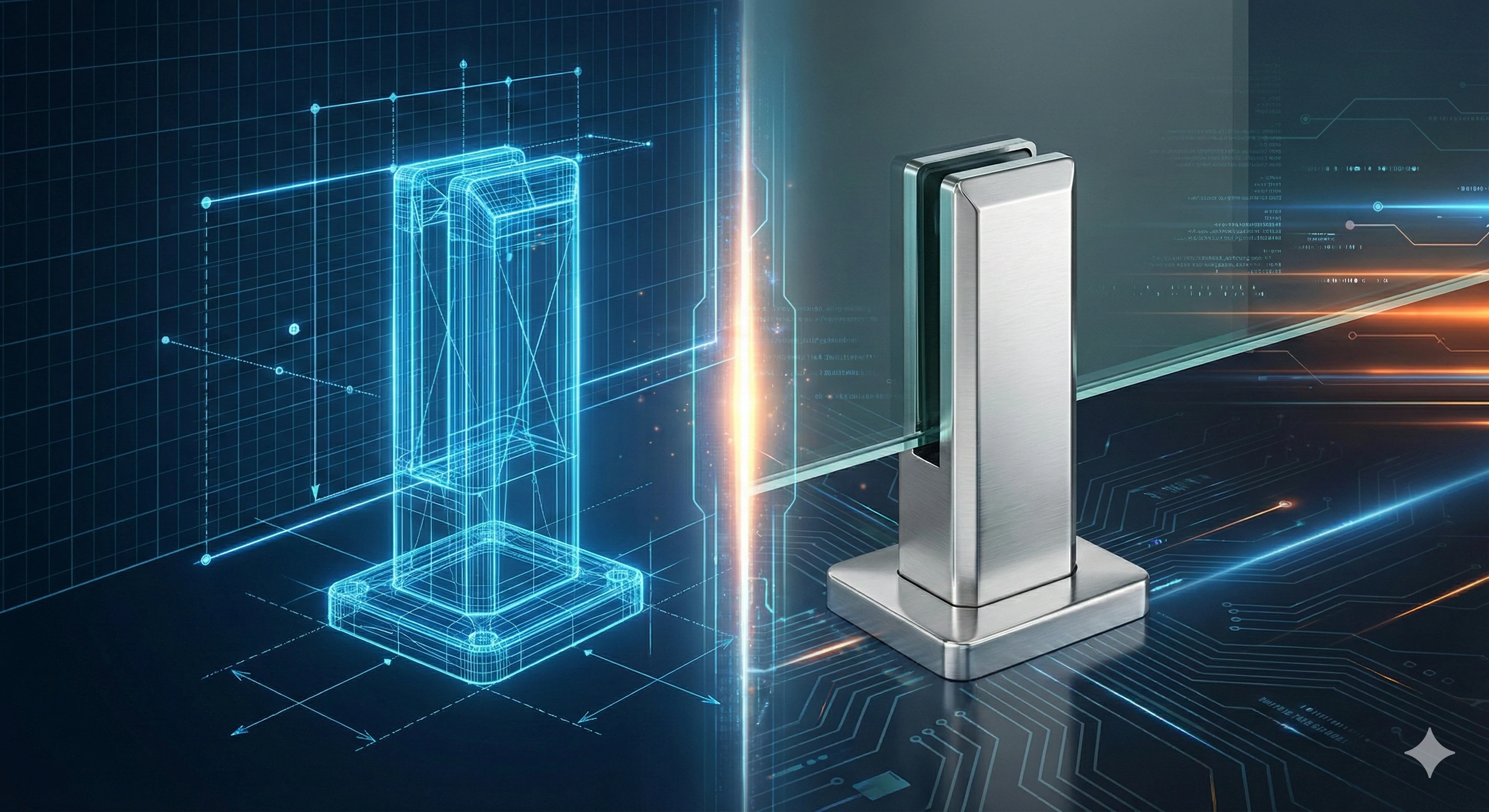
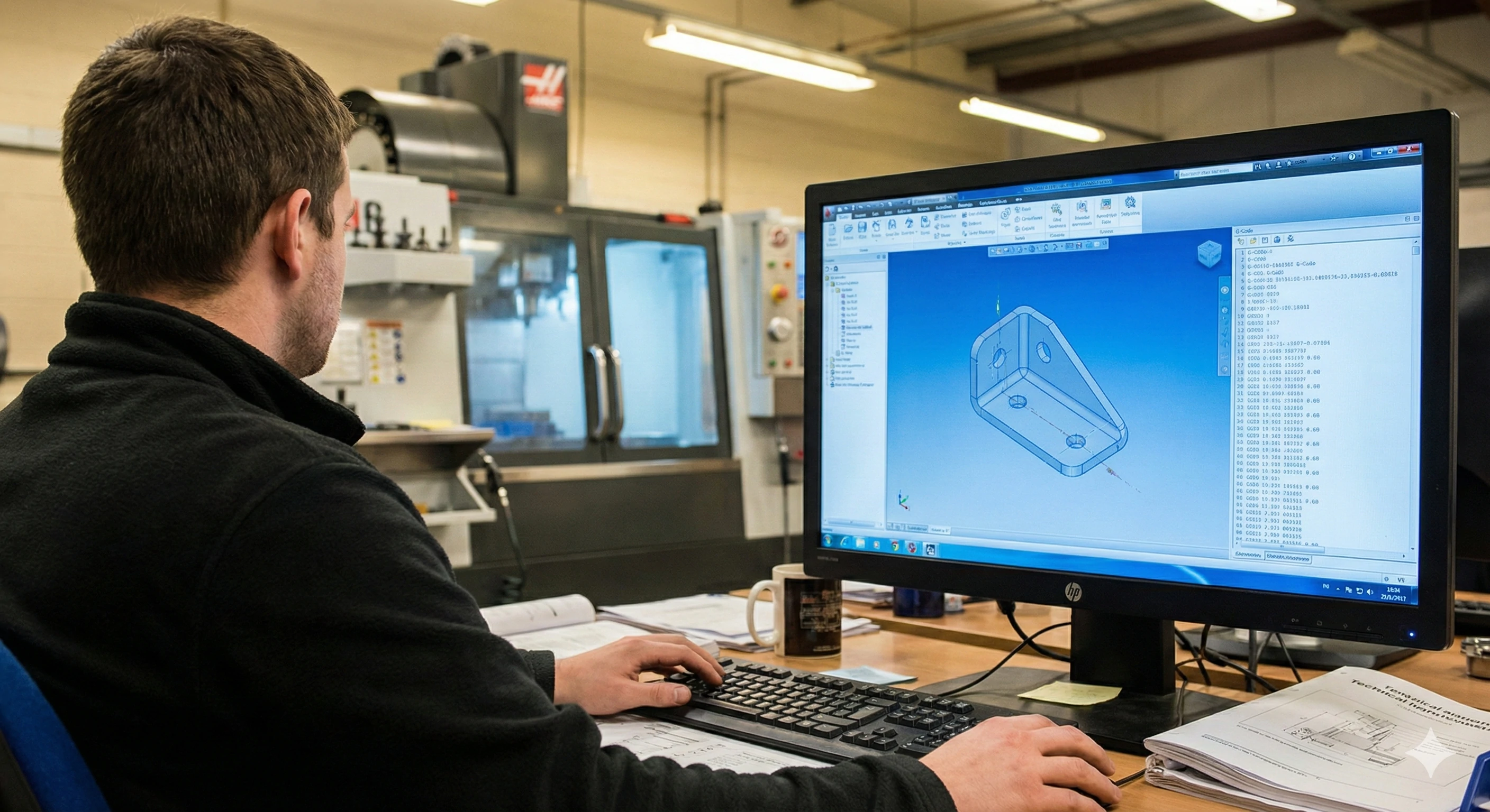
The process begins with a CAD design, which is a 3D model of the part. Next, CAM software converts this model into G-Code, providing coordinates for the machine. We then clamp the raw material into a fixture, and finally, high-speed spindles drive cutters to shave away metal layer by layer.
To truly understand the quality of the parts you are buying, it helps to look deeper into these four stages. The magic lies in the translation between human design and machine execution.
Step 1: Computer-Aided Design (CAD)
Everything starts in the engineering room. Before any metal is cut, our team creates a detailed . This isn't just a sketch; it is a mathematical representation of the part's geometry. We define every curve, hole, and surface. If the CAD model is flawed, the part will be flawed.
Step 2: Computer-Aided Manufacturing (CAM)
This is where the translation happens. We use to take that 3D model and write the "instructions" for the machine. This language is called G-Code. It tells the machine exactly where to move, how fast to spin, and how deep to cut.
Step 3: The Setup
This step relies on skilled technicians. We must secure the raw material—or often, a raw casting—into the machine. We use fixtures to clamp it down tight. If the part vibrates or moves even a hair during cutting, the precision is lost.
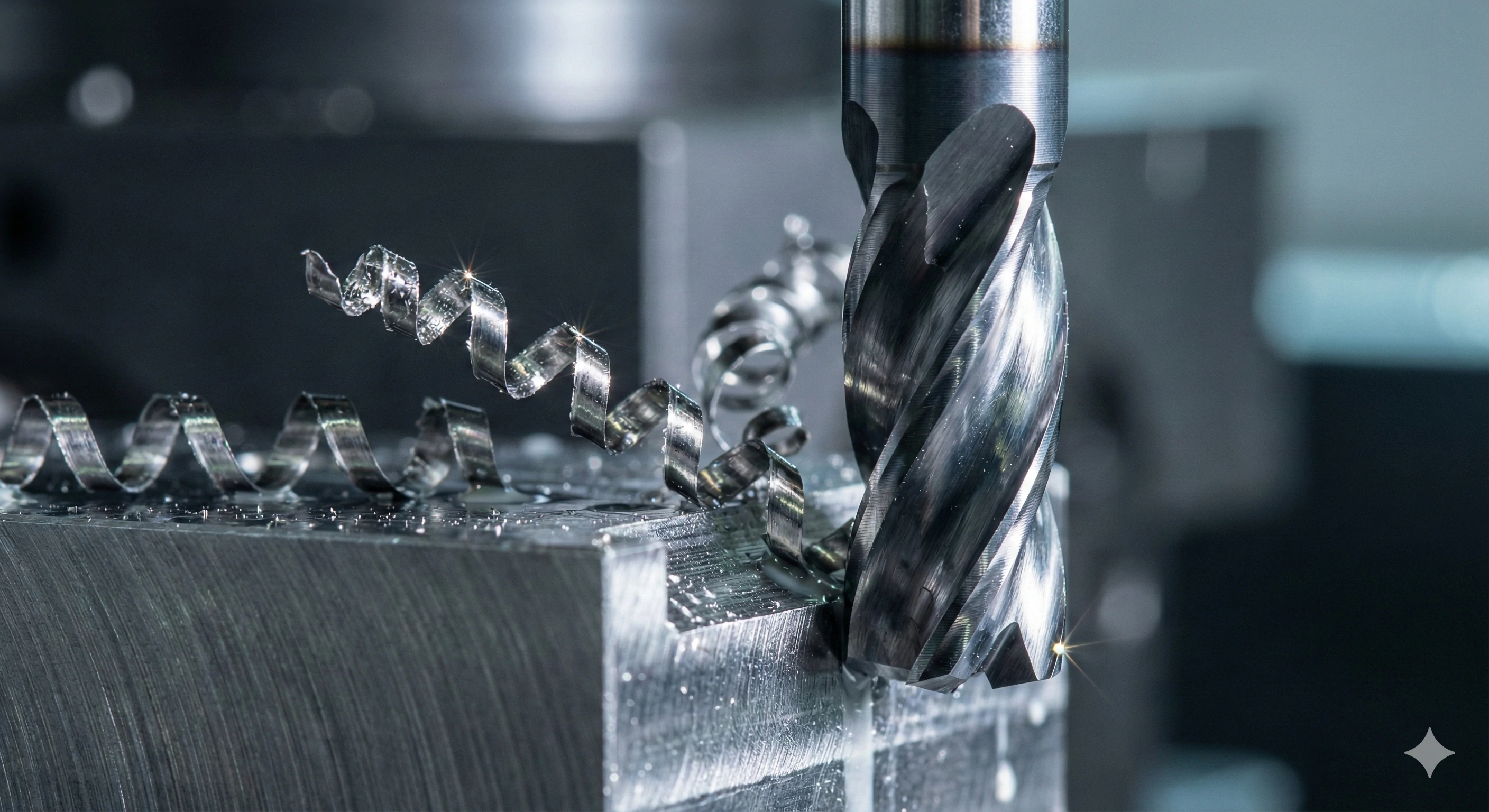
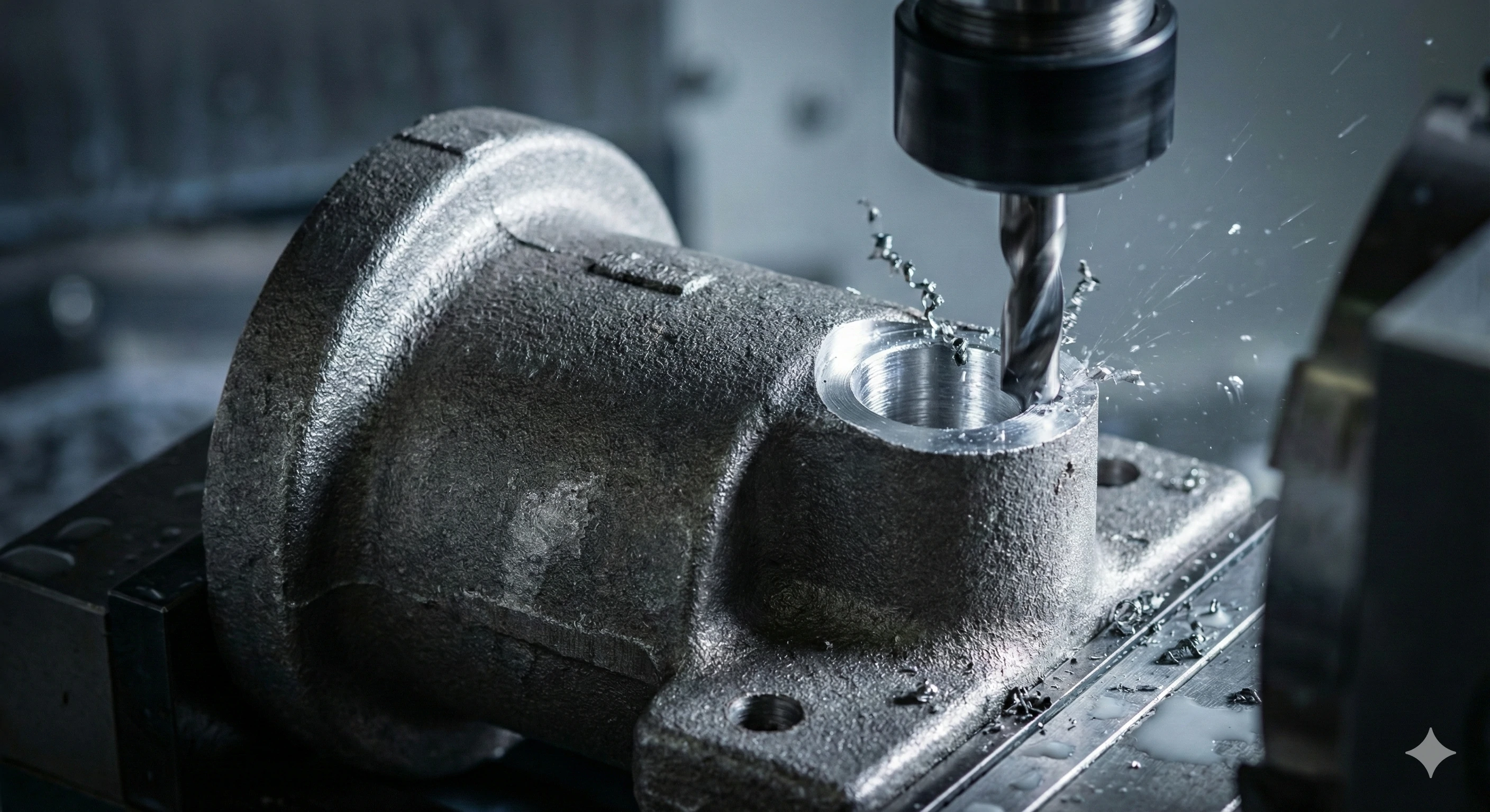
Step 4: The Cut
Finally, the machine takes over. rotate the cutting tools, or the part itself, to remove material. This is "subtractive" manufacturing. Unlike casting, which adds liquid to a mold, machining takes a solid block or rough shape and carves out the final details.
Workflow Summary
| Stage | Action Taken | Primary Tool/Software |
|---|---|---|
| Design | Creating the 3D geometry | CAD Software |
| Programming | Writing the machine instructions | CAM Software / G-Code |
| Setup | Securing the workpiece | Fixtures & Clamps |
| Machining | Removing the material | CNC Machine & Cutters |
What Are the Key Types of CNC Machining Used in Manufacturing?
We utilize various machines on our production line because no single tool can do everything. For a buyer, it can be confusing to distinguish between milling, turning, and multi-axis work. However, choosing the wrong method can lead to inefficiencies or higher costs. We analyze every project to determine which machine will yield the best result for the specific shape required.
The three main types are CNC Milling, where the tool spins while the part stays still; CNC Turning, where the part spins while the tool remains stationary; and 5-Axis Machining, where the tool moves in five directions simultaneously to create complex, organic curves.
Let's dive deeper into which machine is used for which application. Understanding this helps you communicate better with your suppliers.
CNC Milling
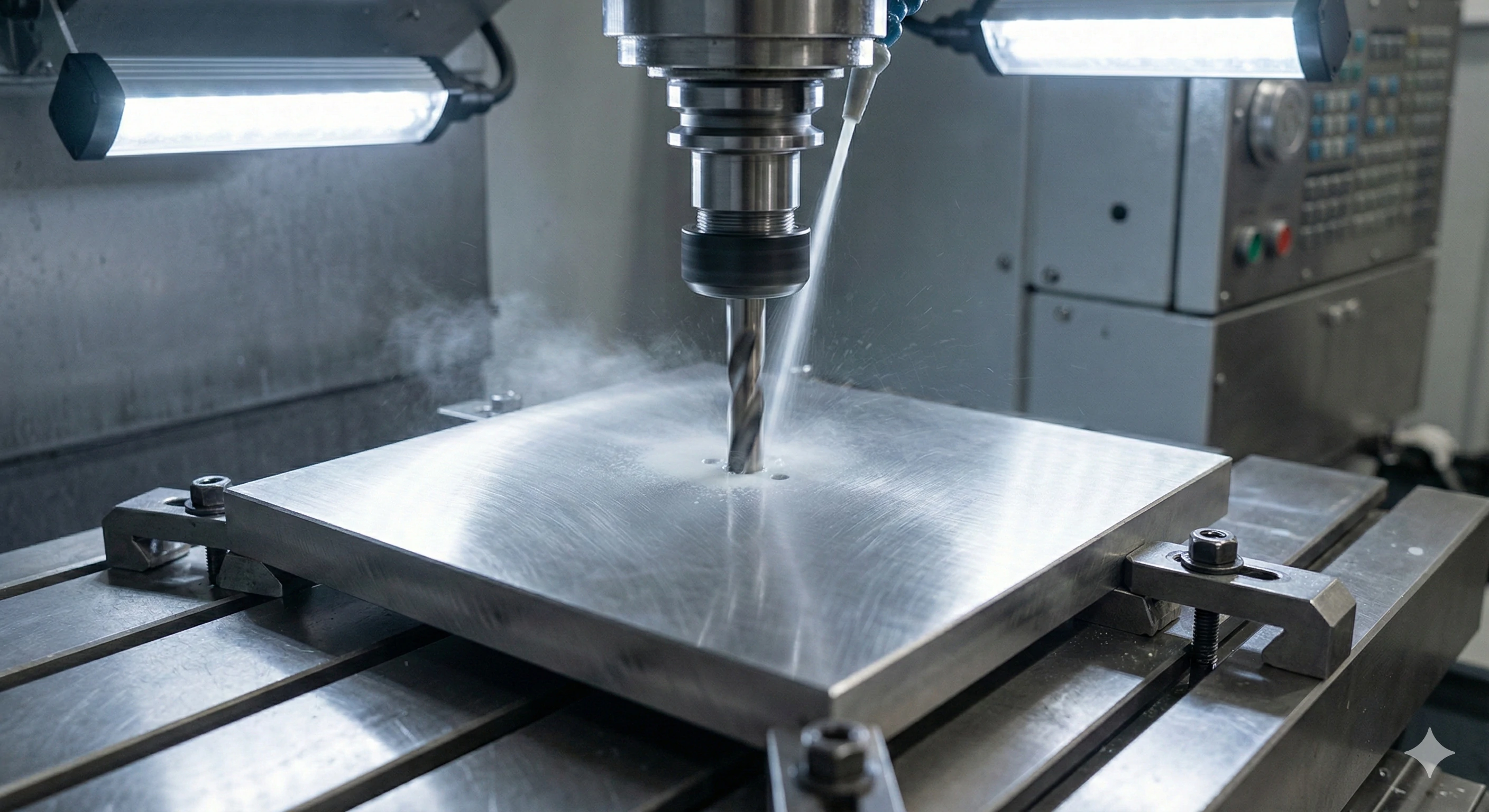
In milling, the workpiece is clamped to a table and does not move (except perhaps sliding along X or Y axes). The spins at high speeds. We use this primarily for square or flat parts.
-
Best for: Cutting flat surfaces, drilling holes, and cutting slots.
-
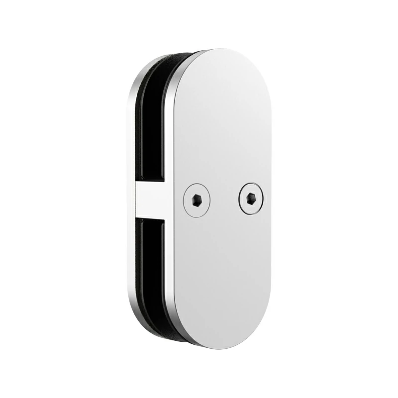
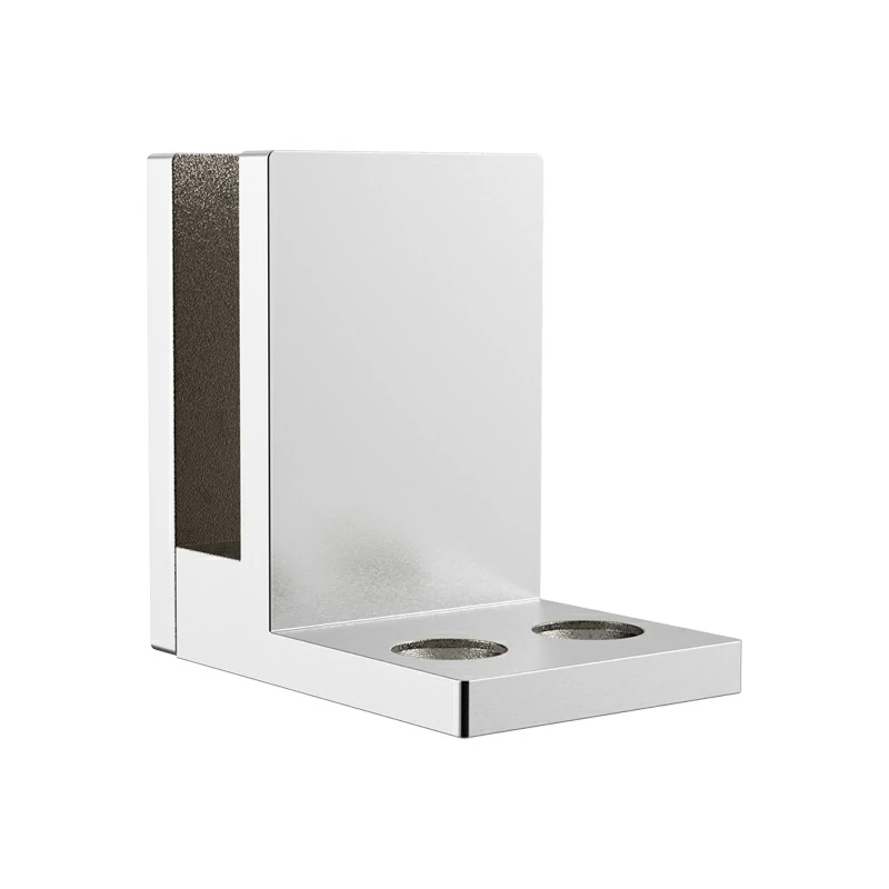
Example: The base plate of a Glass Spigot. We need to drill four precise holes for mounting, and milling is the most efficient way to do this.
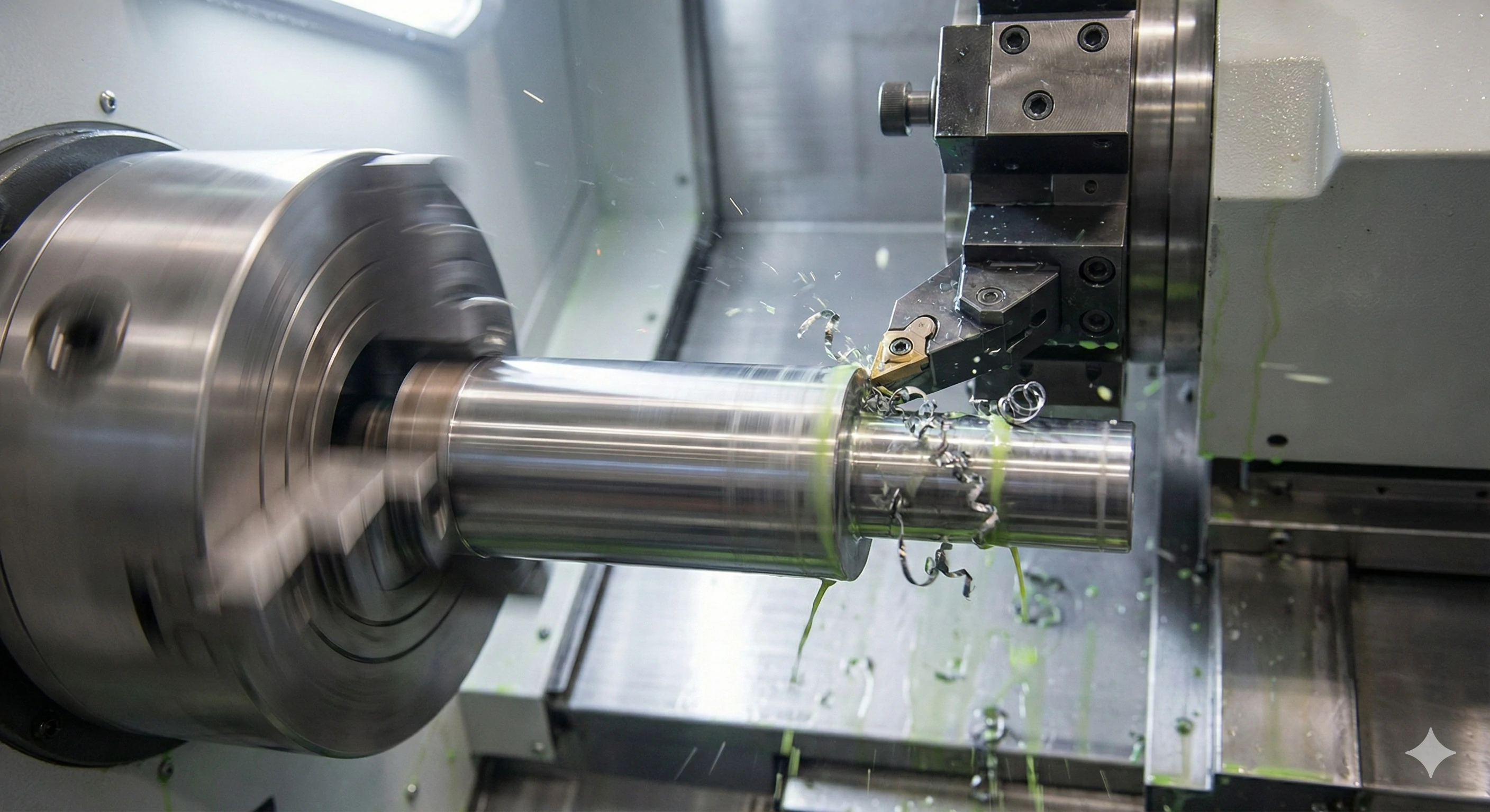
CNC Turning (Lathes)
Turning is the opposite. The part is attached to a spinning chuck, and the cutting tool moves against it. This is similar to how a potter shapes clay on a wheel.
-
Best for: .
-
Example: Pump Shafts or Round Standoffs. If the part is round, a lathe is usually the best choice.
5-Axis Machining
This is the high-end of machining. Standard machines operate on 3 axes (X, Y, Z). A 5-axis machine adds rotation and tilt. This allows the tool to approach the part from almost any angle without having to stop and re-clamp the material.
-
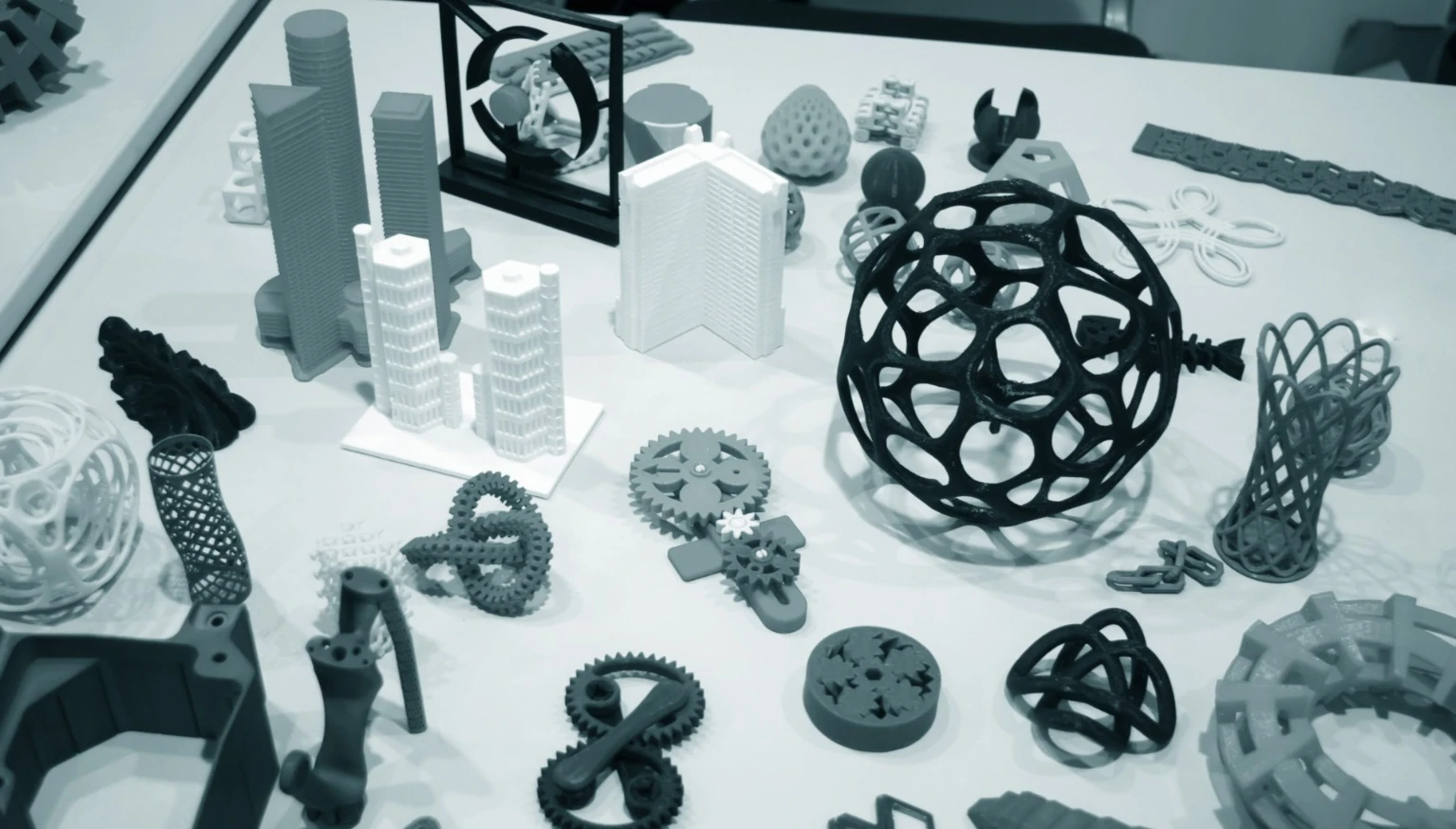
Best for: Complex geometries and organic shapes.
-
Example: Impeller Blades. The curves are too complex for a standard mill.
Machine Selection Guide
| Machine Type | Movement Dynamics | Ideal Application | Real-World Example |
|---|---|---|---|
| CNC Mill | Tool spins, part is static | Flat surfaces, pockets | Glass Spigot Base |
| CNC Lathe | Part spins, tool is static | Cylindrical shapes | Pump Shafts |
| 5-Axis | Multi-directional movement | Complex curves | Impeller Blades |
What Defines High Precision and Why Do Tolerances Matter?
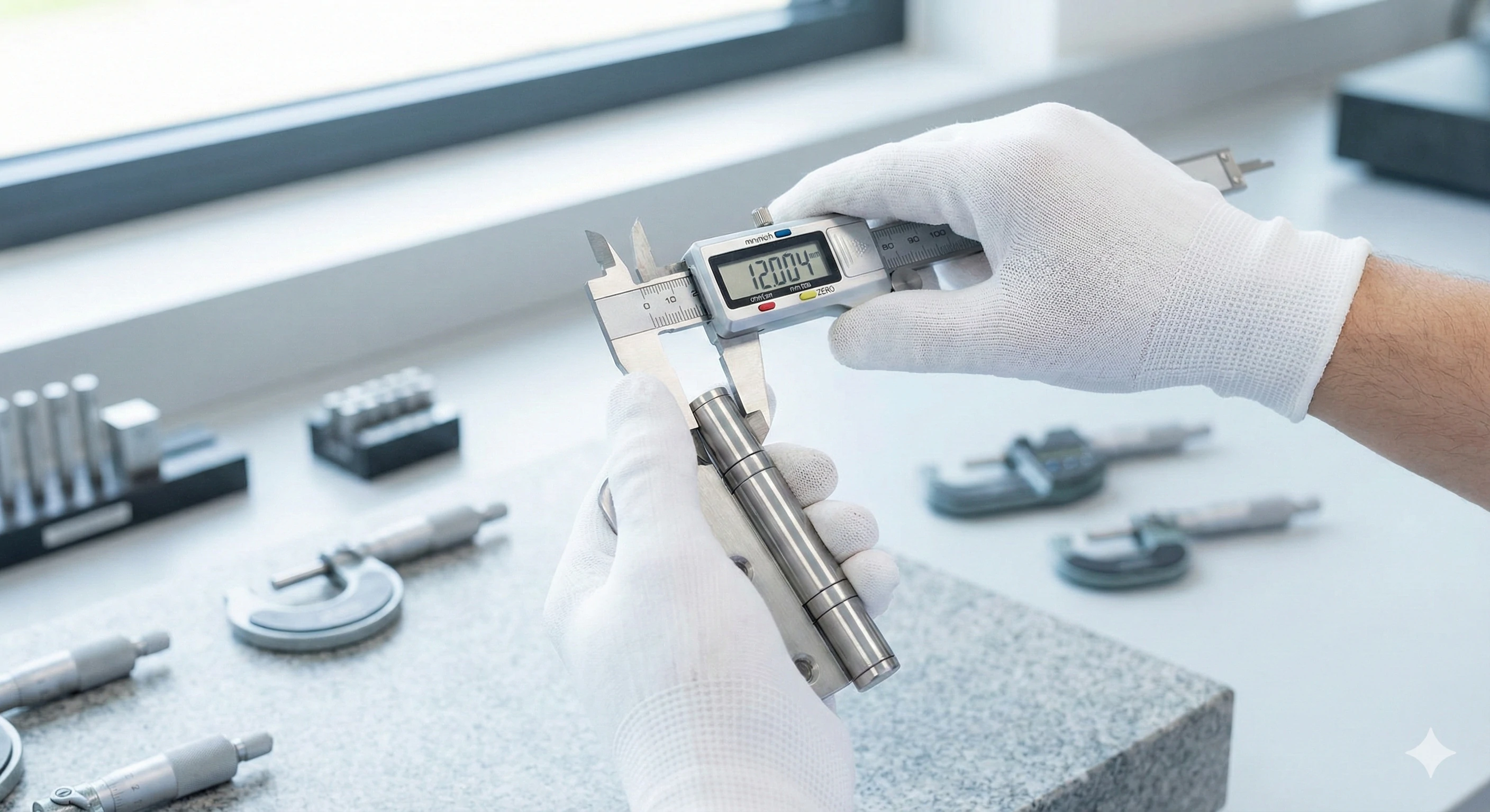
In our , we treat the word "precision" with immense respect. A "pretty good" fit isn't enough when you are building safety-critical hardware like glass railings. We have seen competitors deliver products that look fine to the naked eye but fail during installation because the holes are off by a fraction of a millimeter. This leads to frustrated contractors and returns.
Standard machining cuts to about +/- 0.1mm, roughly the thickness of a sheet of paper. High precision machining tightens this significantly, hitting tolerances of +/- 0.005mm to 0.01mm. This level of accuracy is mandatory for parts that must seal tightly or snap together perfectly.
Why do we obsess over numbers that are smaller than a human hair? It comes down to three critical factors: Fit, Seal, and Interchangeability.
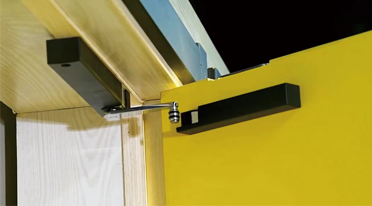
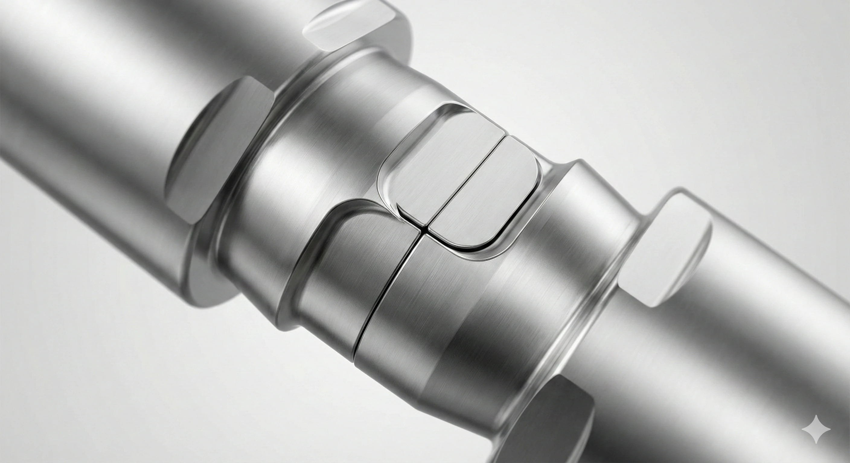
The Perfect Fit
Imagine a hinge pin. If it is too large by just 0.05mm, it won't fit into the barrel. If it is too small, the door will rattle and sag. Precision machining ensures that parts mate together with a satisfying "click" rather than requiring a hammer to force them in.
Creating a Seal
For our clients in the fluid industry, surfaces must be perfectly flat. If a pump casing has a variance on the mating surface, liquid will leak under high pressure. Precision machining creates surfaces so flat they form a seal, preventing leaks and equipment failure.
Interchangeability
This is vital for mass production. If you buy 1,000 units from us, Unit #1 must be identical to Unit #1,000. You cannot have "custom fit" parts in a mass manufacturing environment. Precision ensures that any replacement part you order next year will fit the system you install today.
Understanding the Scale
-
Standard Machining: +/- 0.1mm (Paper thickness)
-
Precision Machining: +/- 0.01mm (1/10th of a paper thickness)
-
Human Hair: Approx. 0.07mm wide
How Do Casting and Precision Machining Work Together?
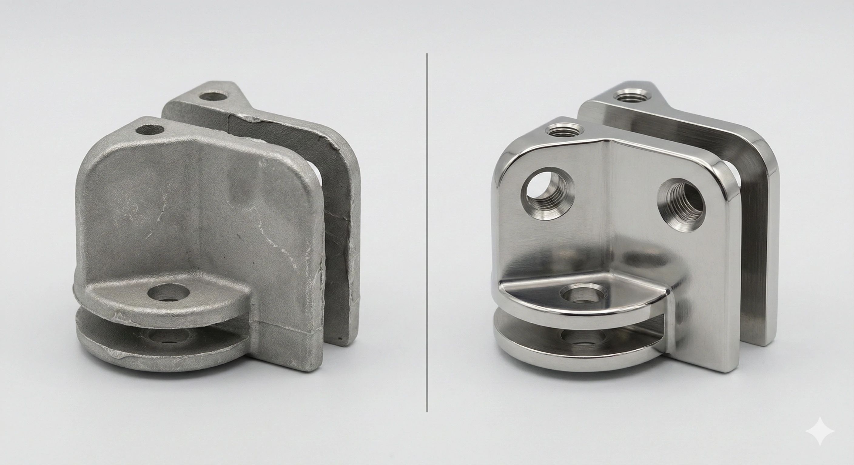
We often find ourselves correcting a common misconception: the "Billet Myth." Many buyers believe that the highest quality parts must be cut from a solid block of metal (billet). While this works, it is incredibly wasteful and expensive. We prefer a smarter approach that saves our clients money without sacrificing quality. By combining two technologies, we get the best of both worlds.
We utilize a "Near-Net-Shape" solution where investment casting creates the part's form to 95% completion. Then, we use CNC precision machining to finish the critical 5%, such as threads and bores. This strategy delivers CNC-level precision while avoiding the 60% material waste typical of machining from solid blocks.
This combination is our Unique Selling Proposition (USP). Here is why this hybrid approach is superior for most hardware applications.
The Problem with Billet (Solid Block)
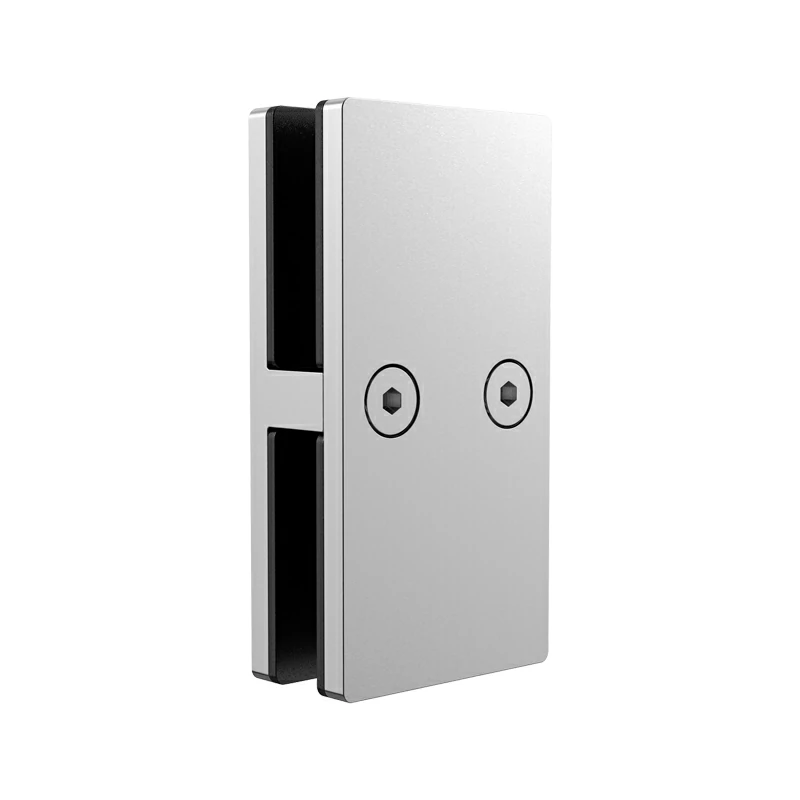
If you want to make a complex shape like a glass clamp from a solid block, you have to cut away a lot of metal. Often, 60% or more of the material turns into scrap chips on the floor. You are paying for stainless steel that ends up in the recycling bin.
The Near-Net-Shape Solution
Instead, we start with . We pour liquid metal into a mold that looks almost exactly like the final part. This gets us the general shape. We call this "Near-Net-Shape."
Once the casting cools, it is rough. It doesn't have the tight tolerances yet. That is when we move it to the CNC Machine. We only machine the areas that matter:
-
The threads for screws.
-
The bores for pins.
-
The flat surfaces for mounting.
The "Best of Both Worlds" Benefit
This method gives you the complex geometry of casting (which is hard to machine) with the and accuracy of CNC. It lowers the cost per unit significantly because there is less waste and less machine time required.
Process Comparison Table
| Feature | Machining from Solid (Billet) | Casting + CNC Machining |
|---|---|---|
| Material Waste | High (60%+) | Low (<5%) |
| Cost | Expensive (Time + Material) | Cost-Effective |
| Geometric Complexity | Limited by tool access | Unlimited (Liquid fills any shape) |
| Precision | Excellent | Excellent (on machined areas) |
Conclusion
We believe that high-quality hardware is the result of smart manufacturing. Casting provides the freedom of form, while CNC precision machining provides the reliability of function. You generally need both to create a product that is durable, affordable, and precise.
For procurement managers, the key is finding a supplier who can handle both processes in-house. This ensures that if a casting is slightly off, the machining team catches it immediately, rather than shipping defective parts across the ocean.
Frequently Asked Questions
What is the difference between CNC and conventional machining?
Conventional machining relies on a human to move levers by hand. CNC relies on a computer to move the tools. CNC is faster, removes human error, and can run unattended.
What materials can be precision machined?
We can machine almost any solid material. In our industry, we focus heavily on (304, 316, 2205), Aluminum, Brass, and Titanium.
Why is precision machining expensive?
It requires expensive equipment—a good machine costs over $100k—and highly skilled programmers. However, for critical parts, this cost is justified by the reliability and performance you gain.
Footnotes
1. Guidelines for designing parts with complex geometries for CNC machining.
2. Overview of CAD software solutions for industrial design.
3. How CAM software bridges the gap between design and manufacturing.
4. Technical deep dive into high-speed spindle technology.
5. Definitions and mechanics of various milling cutting tools.
6. Understanding CNC turning for cylindrical component manufacturing.
7. Resources and standards for industrial quality control processes.
8. Comprehensive explanation of the investment casting process.
9. Chart and calculator for measuring surface finish quality.