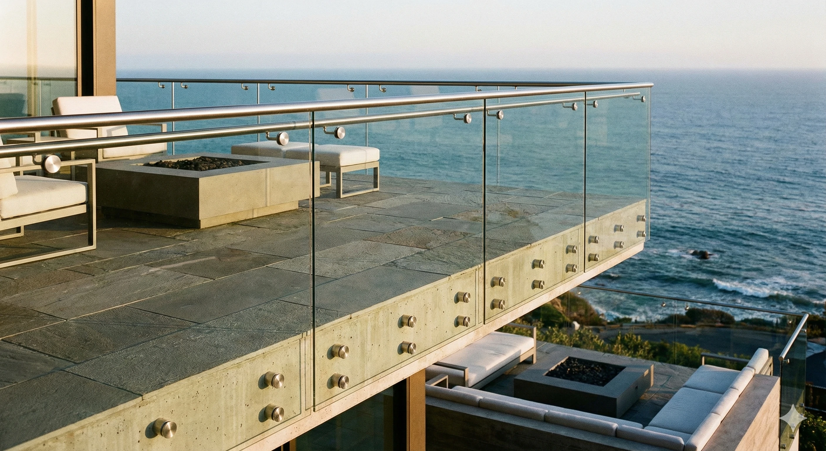

When we review a new glass railing project at our factory, the standoffs may look like the simplest parts on the drawing. However, one mismatch in the hole, gasket, projection, or anchor can stop installation. The problem becomes expensive after tempering, so we confirm the complete assembly before glass production.
Table of Contents
Glass guardrail standoffs are point-fixing components that secure glass panels through predrilled holes to a stair stringer, balcony fascia, deck edge, or landing. A correctly specified standoff system saves floor space and creates a clean frameless appearance, but its glass, fittings, anchors, substrate, and load requirements must be designed as one assembly.
This guide explains what buyers, contractors, and engineers should confirm before ordering.
What Are Glass Guardrail Standoffs?
In our production and export work, we often receive a fitting photo with a request for “the same standoff.” A photo shows the finish, but it does not reveal the anchor, sleeve, glass range, or load path. Missing details can make the replacement unusable, so we identify the complete assembly first.
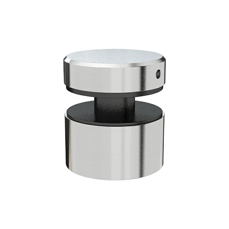
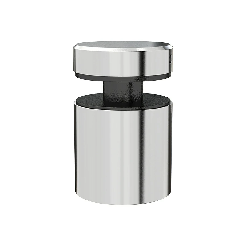
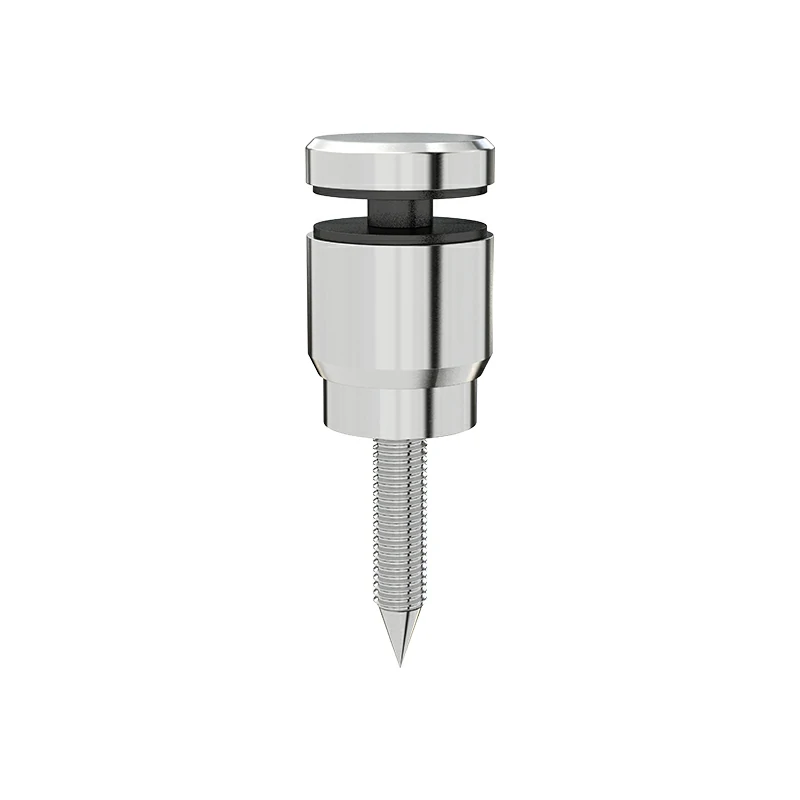
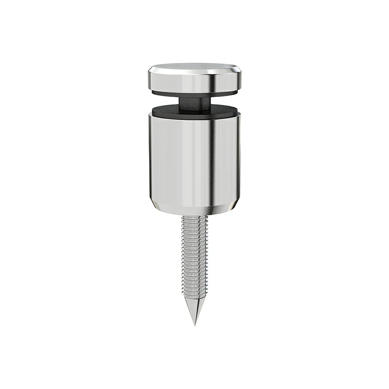
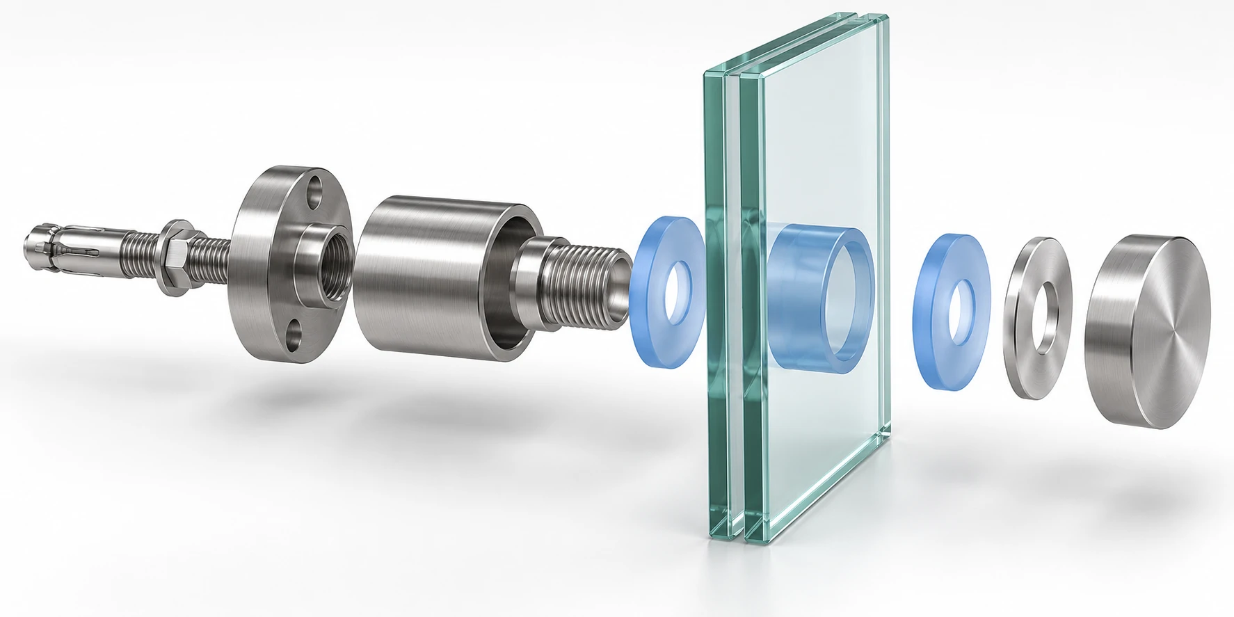
Glass guardrail standoffs are metal point supports that hold a glass guard panel away from the face of a structural substrate. Each fitting normally works with a base, cap, fastener, sleeve, and soft gasket. Together, these parts clamp the panel while keeping metal away from the glass surface and hole edge.
According to LA Railings 1, standoff systems are commonly side-mounted on balconies, decks, staircases, and landings. The mounting hardware stays away from the top of the walking surface, which can preserve usable space and create an open appearance.
How the assembly works
The anchor connects the standoff body to concrete, steel, timber, or another approved substrate. The body sets the distance between the structure and the glass. A sleeve passes through the fabricated hole, while soft gaskets isolate the glass from the metal faces. The cap closes the assembly with controlled clamping pressure.
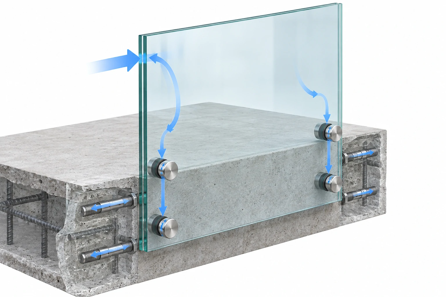
Loads travel from the glass through the point fittings and anchors into the supporting structure. The glass, caps, bodies, anchors, and substrate must therefore be treated as one load path rather than unrelated catalog items.
| Railing approach | Typical mounting position | Main planning concern |
|---|---|---|
| Standoffs | Side of fascia, stringer, or slab | Hole coordinates and anchor capacity |
| Spigots | Top of finished surface | Base fixing and floor waterproofing |
| Base shoe | Continuous channel at the edge | Structural support, drainage, and finishing |
| Posts with infill | Top or side mounted | Post spacing and glass connections |
Standoffs suit projects where floor space and visual openness matter. However, they require close coordination before the glass is fabricated.
Glass Guardrail Standoff Specifications and Material Requirements
When our engineers prepare a quotation, we never identify a fitting only by its diameter or finish. Two standoffs can look identical but use different holes, projections, threads, or grommets. The wrong part may stop installation, so we check a complete specification drawing before production.
Glass guardrail standoff specifications must coordinate the glass build-up, hole diameter, body diameter, projection, cap geometry, sleeve and gasket set, anchor thread, mounting offset, material grade, and finish. Buyers should approve a complete drawing or data sheet because appearance and nominal diameter alone cannot confirm that the hardware, glass, and anchors are compatible.
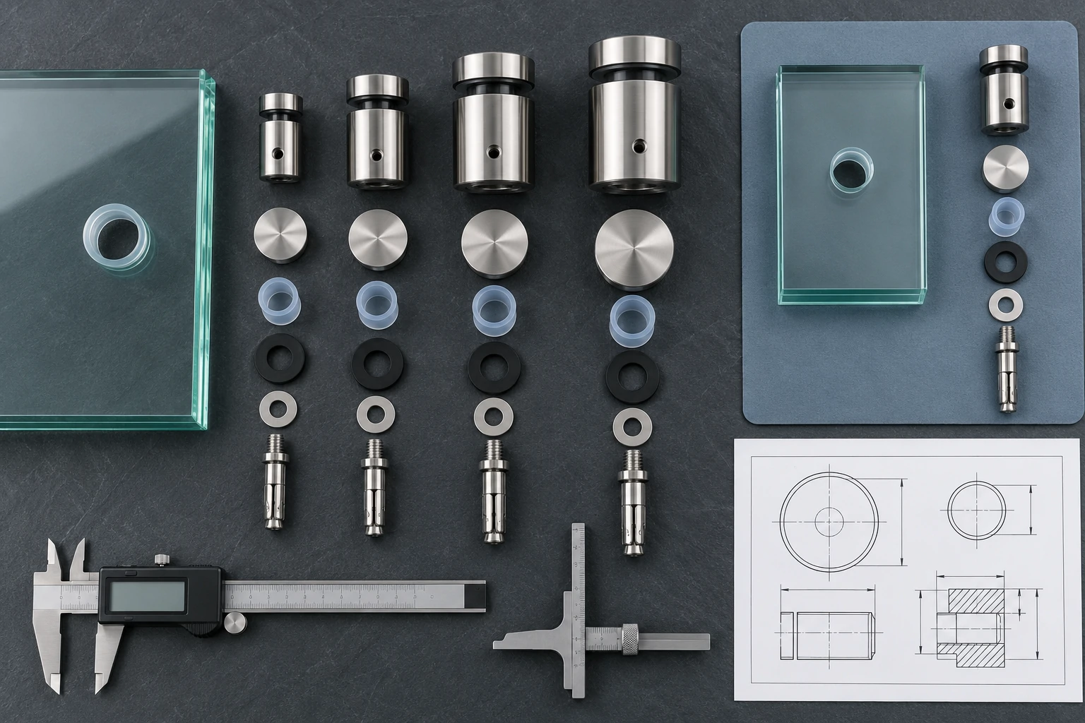
The CRL catalog 2 shows point fittings with many glass ranges, diameters, lengths, threads, and finishes. This variety makes the product code and dimensional drawing essential. Adjustable standoffs can correct limited surface variation, but they cannot repair a wrong glass hole or unsuitable anchor location.
Information required for a reliable quotation
| Specification item | What to confirm | Risk if omitted |
|---|---|---|
| Glass build-up | Total thickness, glass type, and interlayer | Incorrect clamping range |
| Glass hole | Diameter and center coordinates | Sleeve does not fit |
| Standoff body | Diameter, projection, and adjustment | Wrong clearance or appearance |
| Cap and gasket | Shape, material, and thickness | Uneven pressure or metal contact |
| Anchor | Thread, fastener, embedment, and substrate | Incompatible or weak fixing |
| Finish | Alloy, treatment, color, and direction | Corrosion or visual inconsistency |
Start with every glass ply and interlayer. Add the required hole diameter and each hole center measured from finished glass edges. Then define the body, projection, cap, gasket, anchor, substrate, and visible finish. The supplier should place these details on a coordinated drawing before production.
Stainless steel and environmental exposure
Glassupply specifies AISI 316 stainless steel 3 for an adjustable standoff intended for interior and exterior use. Grade 316 is commonly selected for moisture-exposed work, but buyers should still assess coastal air, pools, cleaning chemicals, dissimilar metals, and drainage. “Stainless steel” or a finish color is not a complete material specification.
Glass and code requirements
According to the National Glass Association’s explanation of the International Building Code 4, glass used in guards generally must be laminated and either fully tempered or heat-strengthened, subject to the adopted code and its exceptions. A top-rail-free design may also require approved post-breakage performance.
ASTM E2353 5 covers performance testing of glass in permanent railing systems, guards, and balustrades. ASTM E2358 6 covers performance specifications for these systems. The evidence applies to an assembled configuration, not to the standoff alone. A qualified professional should confirm the local code, glass build-up, guard height, loads, wind conditions, and any proposed substitutions.
| Condition | Main procurement focus |
|---|---|
| Dry interior | Verified alloy, finish consistency, and cleaning method |
| Exterior exposure | Corrosion resistance, drainage, and protected anchors |
| Coastal or pool area | Compatible metals and an enhanced inspection plan |
| No top rail | Approved glass and post-breakage performance evidence |
| High wind or public use | Project engineering and relevant system tests |
How Should Standoff Spacing and Anchors Be Engineered?
When a request says only “four standoffs per panel,” we ask for project data before confirming it. A layout that works on one landing may fail with a wider panel, taller guard, public occupancy, or weak substrate. We therefore verify the calculations and complete load path before approving the quantity.
Standoff spacing and anchors should be engineered from the guard height, glass dimensions and build-up, substrate, edge distances, occupancy loads, wind exposure, and required design loads. No universal spacing rule suits every glass guardrail. The fitting quantity and coordinates must follow project calculations, tested-system limits, and the locally adopted building code.
Follow the complete load path
The design must track forces from the panel into each point fitting, through the anchor, and into the structure. Concrete strength and edge distance affect concrete anchors. Steel thickness and connection details affect a steel stringer. Timber requires suitable structural blocking rather than attachment to cladding or trim.
The Glassupply measuring guide 7 calls for appropriate blocking behind wood fixing locations and provides concrete-edge and glass-hole guidance for its own system. Those dimensions should not be copied into unrelated products. Every manufacturer’s recommendation must be checked against the selected hardware and project engineering.
| Engineering input | Why it changes the design |
|---|---|
| Guard and panel dimensions | Changes leverage, glass stress, and wind area |
| Glass build-up and holes | Controls panel strength and fitting compatibility |
| Standoff projection | Changes the moment transferred to the anchor |
| Substrate and edge geometry | Controls anchor type, embedment, and capacity |
| Occupancy and location | Determines applicable loads and risk level |
| Exterior exposure | Adds wind, corrosion, drainage, and sealing demands |
Changing a panel width, hole pattern, projection, or anchor after approval can invalidate earlier calculations. The purchase order should therefore identify the approved drawing revision and matching engineering documents. If the structure is not finished, the drawing should clearly mark every dimension that still requires field verification.
How Do You Measure, Install, and Buy Glass Guardrail Standoffs?
In our factory, hole coordinates are production-critical because holes cannot be moved after tempering 8. An early drawing can create panels that never align, wasting glass and delaying the project. We prevent this by requiring field-verified dimensions and approved shop drawings before releasing glass production.
Glass guardrail standoffs should be purchased as a documented system, measured from the finished structure, and installed with the specified anchors, sleeves, and gaskets. All glass holes must be made before tempering. Field dimensions, slopes, cladding, edge clearances, anchor positions, engineering documents, and shop drawings should be approved before glass production begins.
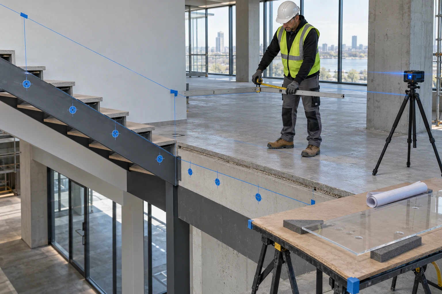
The Glassupply guide requests clear span and stair measurements, followed by shop-drawing review before production. The same controlled sequence is useful for any custom standoff system.
Measurement and installation workflow
- Survey the finished substrate, stairs, nosings, slopes, and cladding.
- Confirm that every proposed anchor zone is structural and accessible.
- Coordinate standoff centers, glass edges, joints, and clearances.
- Approve shop drawings or a full-size template before glass fabrication.
- Install anchors and bodies using the specified method.
- Fit every sleeve and gasket so no metal touches the glass.
- Align panels only within the approved adjustment range.
- Tighten caps by the manufacturer’s stated method or torque.
- Inspect the completed guard and record maintenance requirements.
Every exterior fascia penetration is also a building-envelope detail. The designer should coordinate compatible sealing, drainage, and metal isolation to reduce concealed water entry and corrosion. An installer should never force alignment by over-tightening a cap against the glass.
Supplier documentation checklist
| Document or evidence | Why it matters |
|---|---|
| Assembly drawings | Confirms holes, threads, gaskets, and offsets |
| Material declaration | Identifies the specified alloy and finish |
| Glass schedule | Links each panel to its build-up and location |
| Anchor specification | Defines substrate, fastener, and installation limits |
| Engineering calculations | Supports the project load path |
| ASTM evidence where applicable | Supports claims for the tested configuration |
| Installation instructions | Controls fitting, tightening, and inspection |
Test evidence should be relevant to the proposed glass, standoff layout, and anchor condition. Buyers should also confirm revision control, spare gaskets and caps, packaging protection, quality records, and technical support.
After installation, inspections should check for loose caps or anchors, displaced gaskets, metal-to-glass contact, chipped glass edges, corrosion, coating damage, and water entry. Cleaning products must suit the finish. Any tightening should follow the system supplier’s method rather than uncontrolled force.
Conclusion
Glass guardrail standoffs create a clean, space-saving frameless design, but success depends on more than the visible cap. The glass, holes, gaskets, standoff dimensions, anchors, structure, exposure, testing, and installation must work as one system. Contact Aleader for a quotation, dimensional review, product catalog, or compatible glass railing fittings for your balcony, deck, staircase, or landing project.
Footnotes
1. LA Railings documents standoff systems for stairs, balconies, decks, and related guard applications. ↩︎
2. CRL’s official catalog illustrates the dimensional and finish variety available across glass-rail standoff fittings. ↩︎
3. Glassupply lists AISI 316 and interior/exterior use for its adjustable glass-rail standoff. ↩︎
4. NGA summarizes IBC requirements for laminated, tempered or heat-strengthened glass guards and post-breakage performance. ↩︎
5. ASTM E2353 defines performance test methods for glazing in permanent railing systems, guards, and balustrades. ↩︎
6. ASTM E2358 specifies performance requirements for glazing used in permanent railing systems, guards, and balustrades. ↩︎
7. Glassupply’s guide covers blocking, concrete edge distance, hole spacing, stair measurements, and drawing review. ↩︎
8. Glassupply states that cutting, polishing, and drilling must be completed before glass tempering. ↩︎