We see pipeline failures too often when inspecting . Using the wrong valve type leads to devastating leaks, costly downtime, and expensive mechanical repairs. When we engineer and cast fluid control systems at our factory, we know that selecting the right valve is the beating heart of safe operations. Let's fix this confusion and ensure your next installation performs flawlessly.
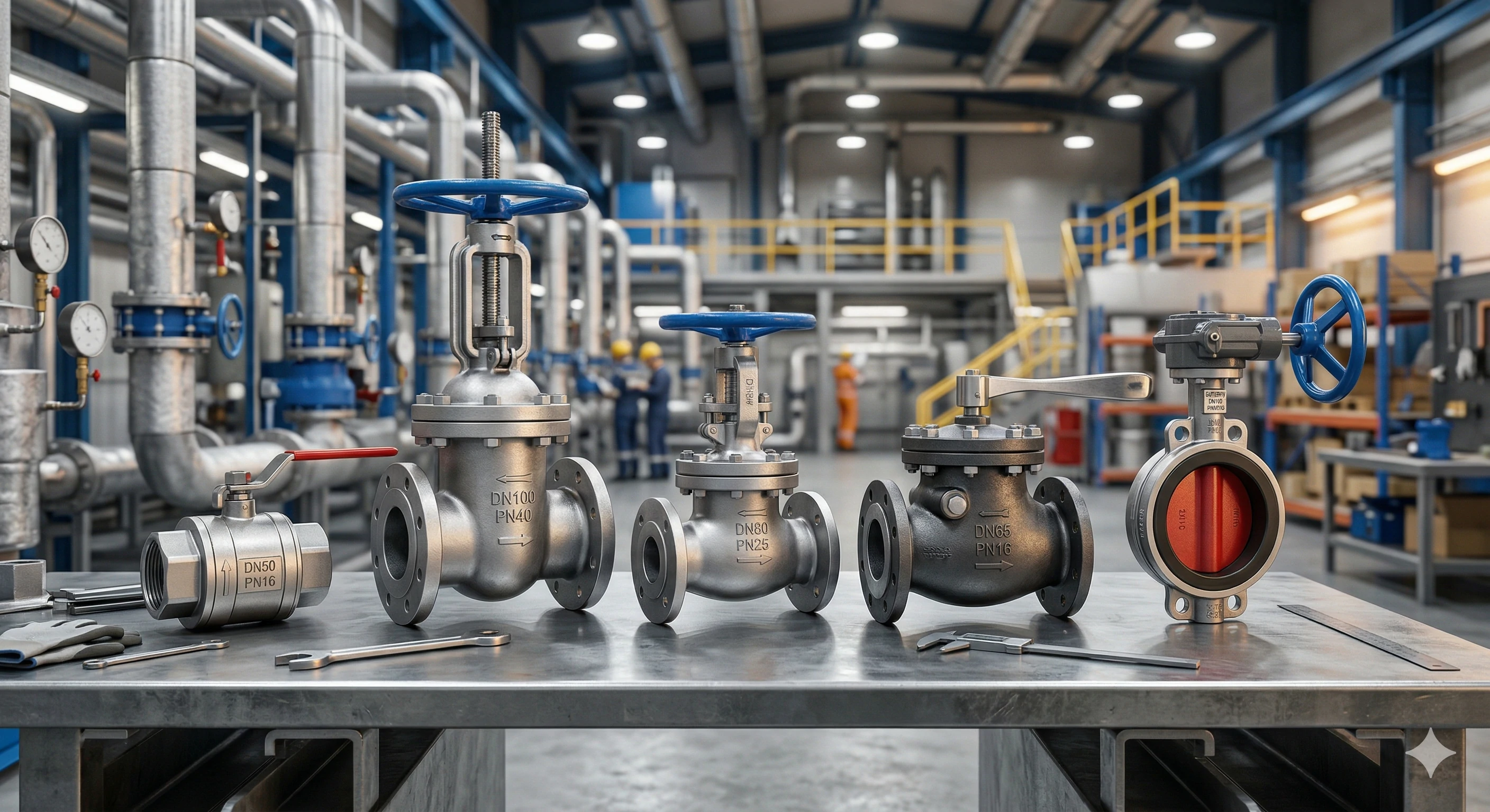
The five main types of industrial fitting valves are ball valves for quick shut-off, gate valves for unobstructed flow, globe valves for precise throttling, check valves for preventing backflow, and butterfly valves for saving space in massive pipelines.

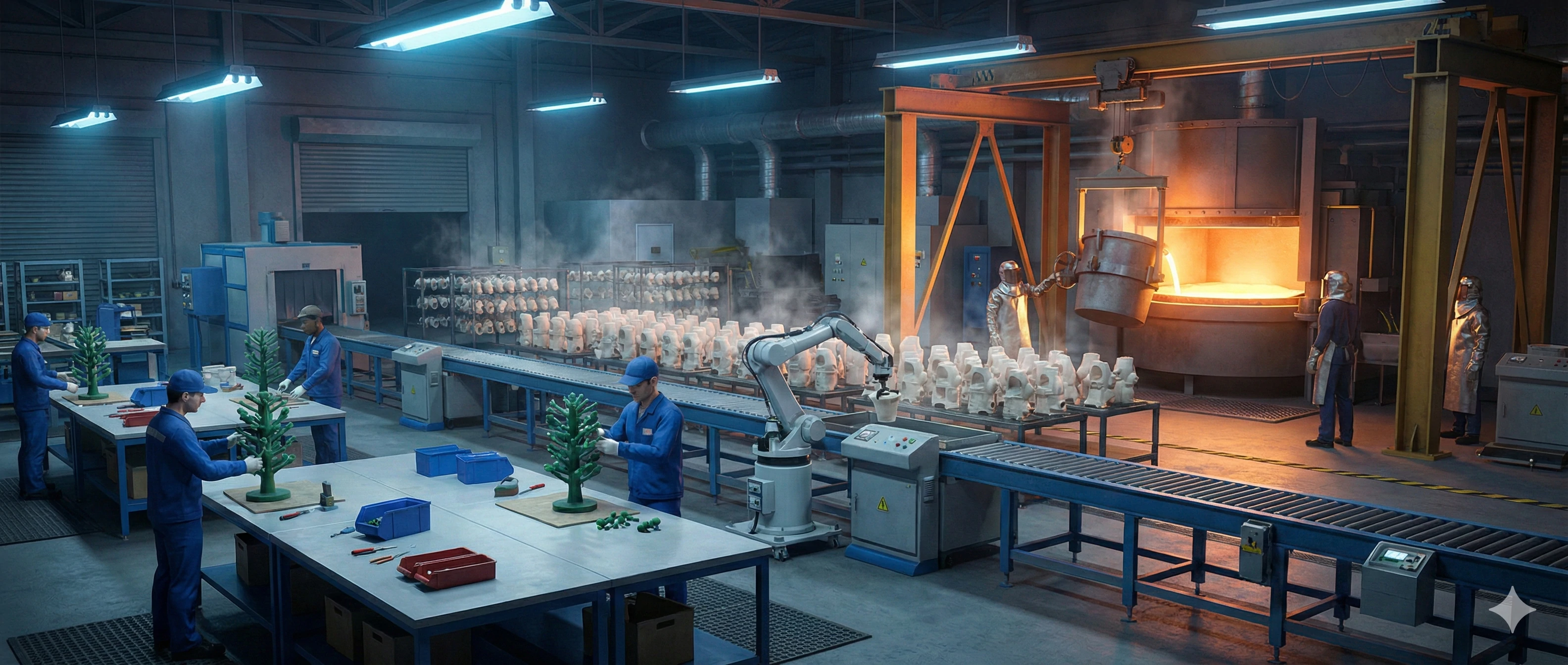
Selecting the correct mechanical function guarantees long-term performance and safety. This guide breaks down these primary categories by their mechanical function, their ideal applications, and the precision manufacturing required to build them.
What Are Ball Valves Used For?
Clients often ask us for a valve solution that stops fluid flow instantly without leaking under high pressure. We know a slow or incomplete shut-off can cause dangerous spills or system pressure issues. In our production lines, we precision-machine these specific valves to solve the critical need for rapid, reliable isolation in .
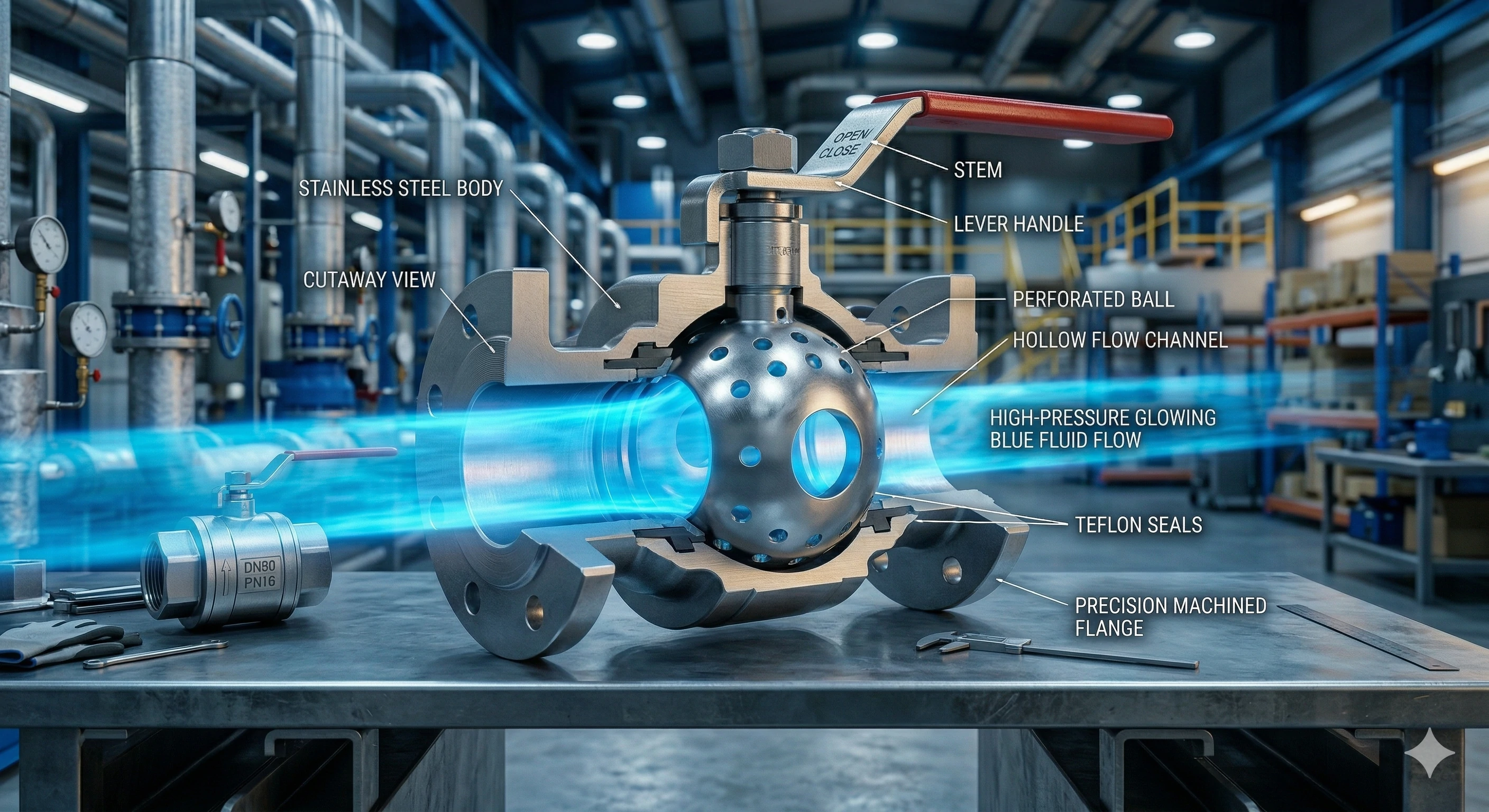
Ball valves use a hollow, perforated, pivoting ball to control flow. A simple 90-degree quarter-turn of the handle completely opens or closes the valve. They are best for absolute shut-off and rapid operation, offering a tight seal.
Understanding the internal mechanics of this quick shut-off mechanism is vital for any procurement manager. The core component is a highly polished metal sphere with a hole drilled straight through its center. When the valve is in the open position, this hole aligns perfectly with the pipeline, allowing fluid to pass through without any obstruction. This creates a , meaning the system maintains maximum efficiency. However, when the operator turns the handle 90 degrees, the solid side of the ball blocks the flow completely.
The Manufacturing Challenge for Ball Valves
Creating a reliable, leak-proof seal is the hardest part of building this component. The metal ball must be CNC-machined to achieve perfect spherical sphericity. It must seat flawlessly against the located inside the valve body. If the machining process is off by even a single micron, the high-pressure fluid will force its way past the seal and cause a dangerous leak. We ensure our CNC lathes hold incredibly tight tolerances to prevent this failure.
| Feature | Advantage | Disadvantage |
|---|---|---|
| Operation Speed | Very fast 90-degree turn | Can cause water hammer if closed too abruptly |
| Sealing | Excellent tight shut-off | Highly discouraged for regulating or throttling flow |
| Maintenance | Easy to repair and replace | Seats can wear out if highly abrasive media is used |
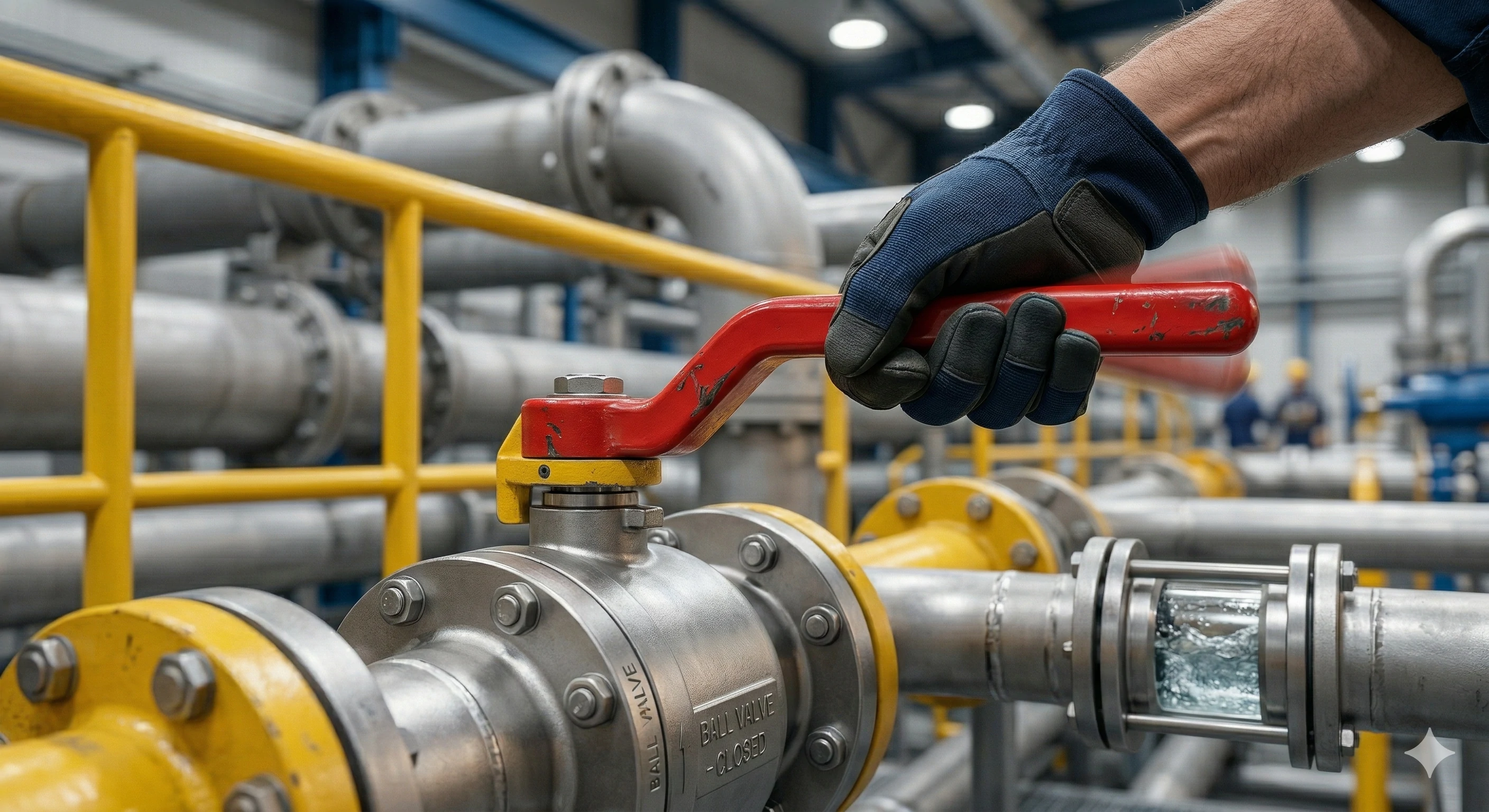
This fast action is why they are standard in emergency shut-off situations. You want a reliable seal when you need to isolate a section of pipe quickly, but you must never leave them partially open.
How Do Gate Valves Work?
We frequently troubleshoot systems handling thick, viscous fluids like heavy oils or . A restricted flow path in these environments creates massive clogs and destroys expensive pumps. When we cast valves for these heavy-duty applications, we focus on providing a completely clear internal pathway to eliminate flow resistance entirely.
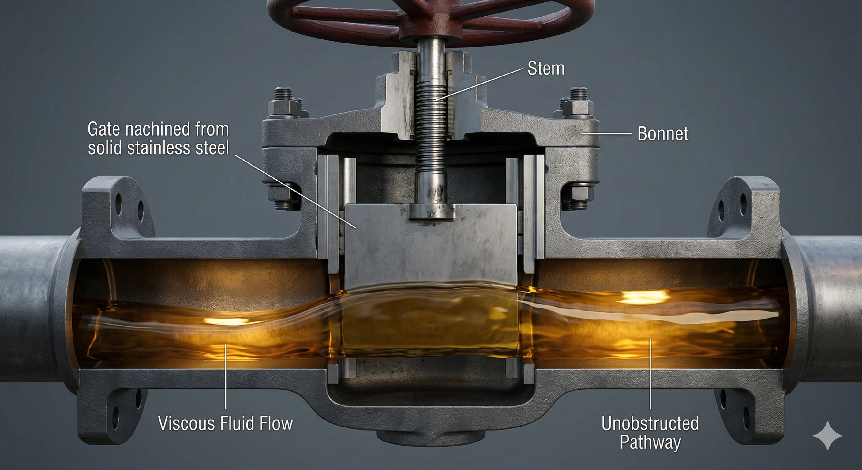
Gate valves work by raising or lowering a flat metal gate via a threaded stem. When fully open, the gate disappears into the bonnet. This creates a straight, unobstructed path for the fluid, making them ideal for thick fluids.
A gate valve operates much like a physical wall moving up and down to block a tunnel. Because the gate is entirely removed from the fluid path when opened, the medium can flow freely. This makes it an excellent choice for on/off applications, especially when dealing with heavy slurries or oils. However, this design means the valve opens and closes slowly, requiring multiple turns of a handwheel. You must never use a gate valve for throttling or regulating flow volume. The high velocity of the fluid hitting a partially opened gate will cause intense vibration and rapid metal erosion, destroying the valve.
Casting Straight Internal Tracks
The manufacturing process for a gate valve requires extreme precision in the foundry. The internal tracks that guide the metal gate up and down must be cast perfectly straight.
If the heavy valve body warps or distorts during the high-temperature casting process, the internal tracks will become misaligned. When this happens, the gate will jam securely in place, and the operator will not be able to close the valve during an emergency. By utilizing strict temperature controls and high-quality mold materials, we prevent this warping and ensure smooth operation for the lifetime of the product.
What Is the Function of a Globe Valve?
When our engineers review designs for steam lines or , regulating the exact volume of fluid is always the top priority. Using a standard on/off valve for this task ruins the internal seals very quickly. Our specialized investment casting process allows us to create valves specifically engineered to throttle and regulate flow safely and accurately.
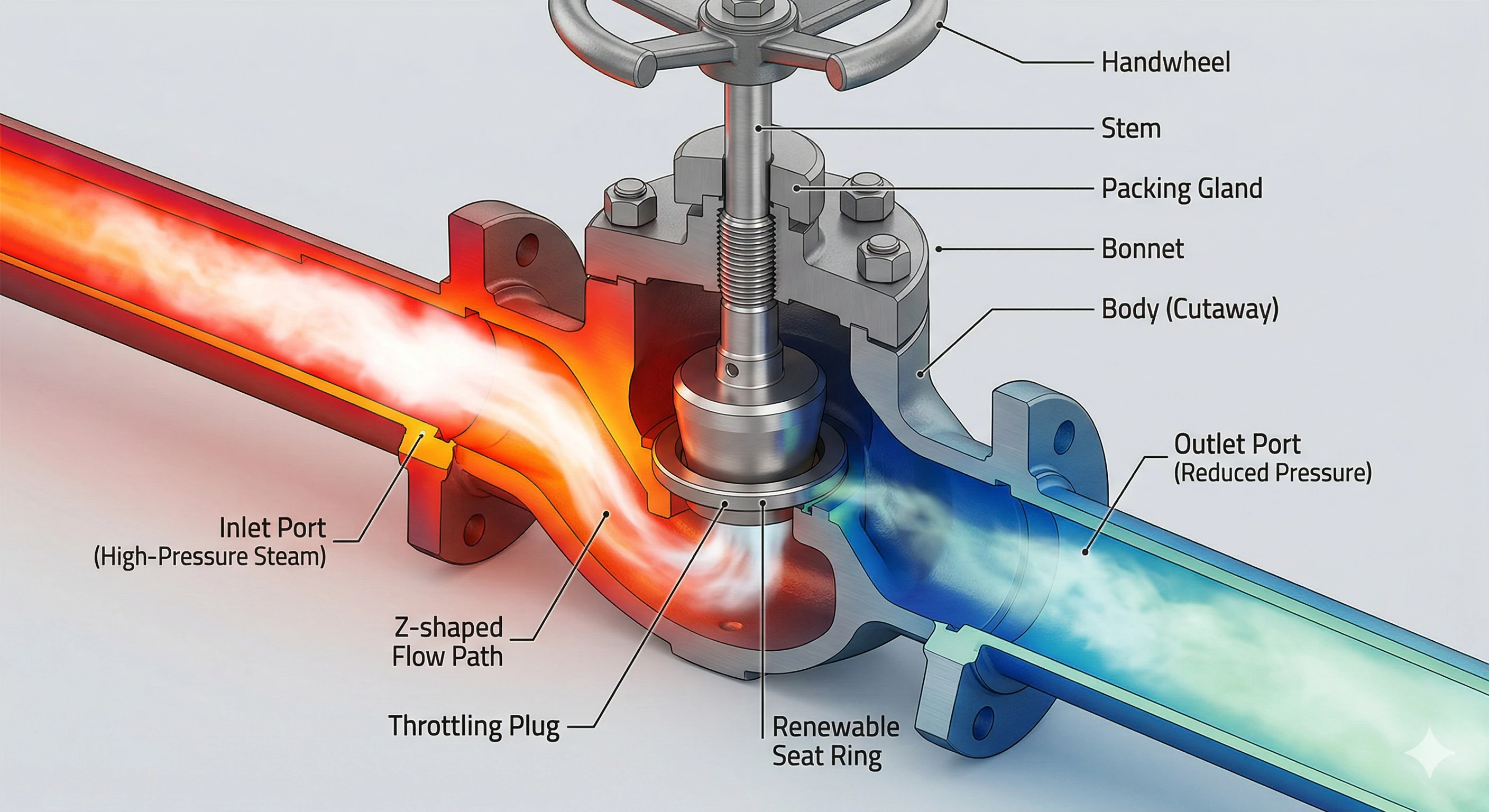
Globe valves feature an internal Z-shaped or S-shaped fluid pathway. A plug lowers into a horizontal seat to restrict the flow. They are specifically designed for precisely regulating and throttling flow volume in steam lines and cooling water systems.
Visualizing how the water flows through a globe valve versus straight past a gate valve is the fastest way for a reader to understand the engineering difference. Fluid entering a globe valve must change direction multiple times, flowing up and over the internal bridge where the seat is located. This creates a higher pressure drop than other valves, but it grants the operator incredible control over the flow rate. As the handwheel is turned, the plug slowly lowers into the seat, gradually restricting the fluid passage without causing damage to the metal.
The Investment Casting Advantage
This precise throttling capability is exactly where investment casting shines.
Creating that complex, curved internal fluid channel requires advanced foundry techniques. We use specialized, water-soluble wax cores during the tooling phase. Once the metal is poured and cooled, the core is dissolved, ensuring the inside channel is perfectly smooth and free of turbulence-causing defects.
| Valve Type | Primary Function | Fluid Pathway | Pressure Drop |
|---|---|---|---|
| Globe Valve | Regulating and Throttling | Z-shaped or S-shaped | High |
| Gate Valve | On/Off Isolation | Straight, unobstructed | Very Low |
| Ball Valve | Quick Shut-off | Straight through ball | Very Low |
If you need to control the exact amount of water moving through a pipe, this is the only correct choice.
Why Are Check Valves Important?
Protecting expensive pump impellers from sudden reverse flow is a top priority for our industrial clients. A massive backflow event can mechanically destroy a pumping system in seconds. We manufacture these automatic flow-control valves to ensure hazardous or high-pressure fluid only travels in one safe direction.
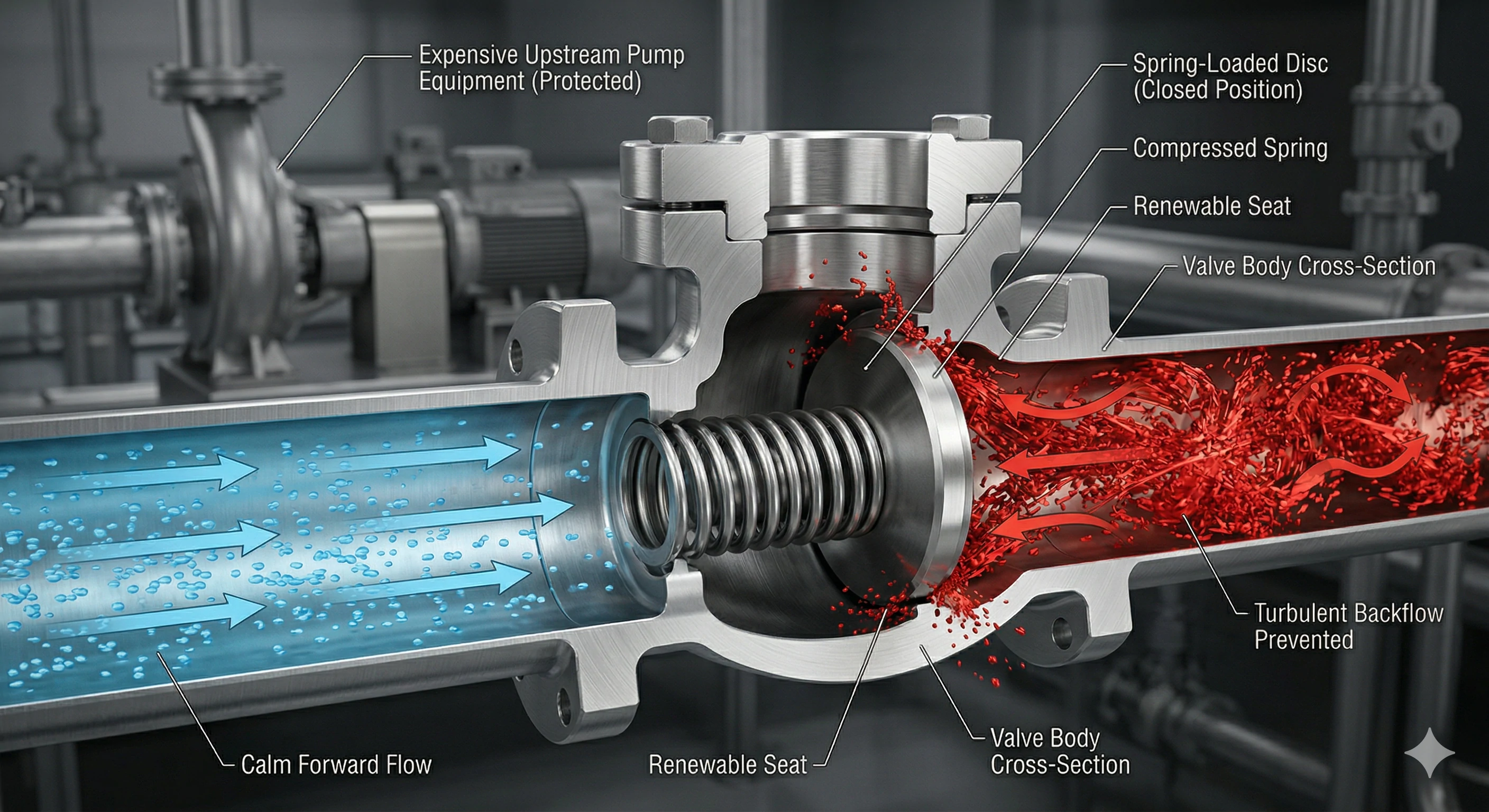
Check valves are fully automatic valves that use fluid pressure to open a flap or lift a spring-loaded disc. If the fluid tries to flow backward, the valve slams shut. They are essential for preventing backflow and protecting expensive equipment.
Unlike other fitting valves, a check valve does not require a human operator or an electronic actuator to function. It relies entirely on the within the pipeline. When the pump is turned on, the forward velocity of the fluid pushes the internal disc or flap open. The moment the pump stops, gravity or the reversing fluid pressure forces the disc back into its seat, sealing the pipe instantly. This simple but robust action prevents contaminated water from flowing backward into clean supplies and stops pressure surges from damaging delicate machinery upstream.
Achieving Low Friction Surfaces
The main manufacturing challenge lies in the sensitivity of the internal components. Because they rely entirely on fluid pressure to operate, the internal surface finish must be exceptionally smooth.
We must achieve a very low Ra value (surface roughness average) to minimize friction. If the internal walls are rough, the disc will stick, requiring a massive pressure drop just to push the valve open. By applying fine machining to the internal hinge pins and seats, we guarantee the valve opens easily and closes tight the moment the flow direction changes.
When Should You Use a Butterfly Valve?
Space and weight constraints in massive municipal water lines create huge structural engineering headaches. Installing heavy, traditional valves requires extra steel supports and drives up project costs significantly. Our solution involves building compact, lightweight valves that still offer reliable, heavy-duty sealing for very large-diameter pipes.
A butterfly valve is a quarter-turn valve using a flat metal disc mounted on a rotating center shaft. They are best used for large-diameter pipes where space and weight are strictly limited, offering a highly compact flow control solution.
The butterfly valve operates similarly to a ball valve, using a quick 90-degree turn to open or close. However, instead of a heavy metal sphere, it uses a thin metal disc positioned in the center of the flow path. When open, the fluid flows around the flat disc. Because the valve body is incredibly narrow—often just a few inches thick even for massive pipes—it takes up very little space. This makes them the standard choice for , shipbuilding, and large HVAC systems where installing a giant gate valve is physically impossible.
Maintaining Concentric Sealing
The manufacturing challenge for a butterfly valve revolves around the perimeter of the disc. The outer edge of the disc must be perfectly concentric to maintain a continuous, 360-degree seal against the rubber or metal seat located inside the valve body.
| Application Factor | Butterfly Valve Benefit |
|---|---|
| Installation Space | Extremely narrow profile saves pipeline space |
| Overall Weight | Lightweight design requires less structural support |
| Operation Speed | Quick quarter-turn operation for fast response |
| Manufacturing Cost | Uses less raw material, making it cost-effective |
If the center shaft is misaligned by a fraction of a millimeter during assembly, the disc will rub unevenly, tearing the rubber seat and causing a permanent leak.
How Do Valves Connect to Pipelines?
Even the highest quality valve will leak if the connection to the surrounding pipe is poorly designed. We frequently see major construction projects delayed because the end connections don't match the site requirements. In our dedicated CNC machining centers, we cut exact threads and face flanges to ensure your installation is completely secure.
Valves connect to pipelines using three main methods. Threaded ends feature CNC-cut internal threads for smaller pipes. Flanged ends use heavy-duty cast rings for massive pipelines. Socket weld ends require the pipe to be welded permanently into the valve.
Choosing the right connection type is just as important as choosing the right valve mechanism. For standard, smaller industrial applications, threaded ends (such as NPT or ) are the most common. The pipe simply screws directly into the valve body. For large-scale industrial systems dealing with high pressure, flanged ends are mandatory. These are heavy-duty cast rings extending from the valve that align with matching rings on the pipe, bolted together with a sealing gasket compressed between them.
Ensuring Perfect Mating Surfaces
For critical applications where absolutely zero leakage can be tolerated—such as toxic chemical lines—socket weld ends are used. The pipe slips into a recessed area of the valve and is permanently welded in place.
This requires highly precise inner-diameter machining at our factory to ensure the pipe fits perfectly before welding. Similarly, for flanged connections, we meticulously CNC-face the flanges to ensure perfect gasket adhesion. A rough flange face will cause the gasket to blow out under pressure, while a perfectly machined face guarantees a secure, long-lasting industrial seal.
Why Do OEMs Trust Investment Cast Valves?
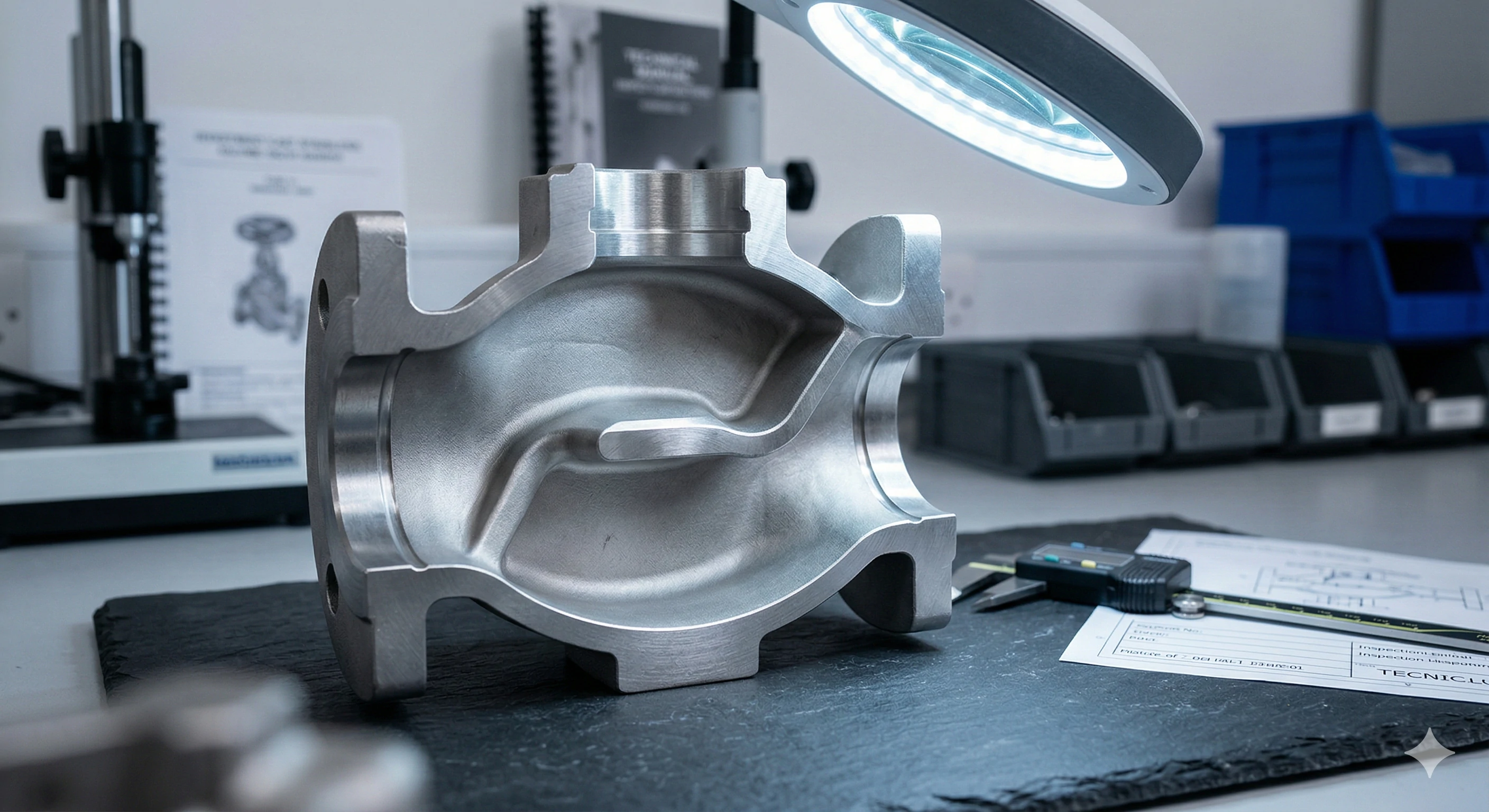
Procurement managers often complain to us about weeping leaks under high pressure when using standard sand-cast hardware. Microscopic porosity in the metal is a hidden defect that ruins system integrity and damages brand reputations. We solve this problem entirely by using advanced precision casting techniques that deliver dense, flawless metal structures.
Standard sand casting leaves microscopic air pockets that cause weeping leaks. Investment cast valves utilize precision lost-wax casting in alloys like Stainless Steel 316. This delivers densely packed, porosity-free valve bodies that guarantee strict tolerances for leak-proof fluid control.
A valve is fundamentally a . When standard sand casting is used, the cooling metal often traps tiny air bubbles, creating a sponge-like network of microscopic porosity. When high-pressure fluids enter the system, they find these weak paths and slowly seep through the solid metal walls. The Aleader solution eliminates this risk by utilizing the lost-wax investment casting process.
Superior Materials and Tight Tolerances
By pouring molten metal into highly detailed ceramic shells, we achieve a much denser, stronger structure. We cast in premium alloys like Stainless Steel 316 and Duplex 2205, which offer incredible strength and corrosion resistance.
Combined with our in-house CNC machining centers, we guarantee the strict dimensional tolerances required for OEM fluid control. Every internal seat, threaded connection, and moving stem is cut to exact specifications. This combination of dense, porosity-free metal and ultra-precise machining ensures that our products perform flawlessly in the most demanding industrial environments.
What Are the Most Common Valve Questions?
Buyers frequently face technical confusion when selecting specific materials or internal port sizes for their engineering projects. Making the wrong choice early on leads to rapid corrosion, system inefficiency, or catastrophic mechanical failure. We compile the data from our global export experience to clarify these critical technical details for you.
Common questions involve regulating water with ball valves, which is highly discouraged. Users also ask about full port versus reduced port designs for flow restriction, and why Stainless Steel 316 is preferred over carbon steel for extreme chemical and rust resistance.
We frequently receive inquiries about specific application boundaries. Below are the most critical questions we answer for procurement teams and engineers.
Can I use a ball valve to control or regulate water flow?
It is highly discouraged. Ball valves are engineered to be strictly fully open or fully closed. If you leave a ball valve partially open to throttle flow, the high-pressure fluid will quickly erode the exposed edge of the internal Teflon seat. This permanently ruins its ability to shut off completely, causing continuous leaks. You should always use a globe valve for regulating flow.
What is a "Full Port" vs. a "Reduced Port" valve?
In a "Full Port" valve, the internal diameter of the valve is exactly the same as the internal diameter of the connecting pipe. This means there is zero restriction of flow and no pressure drop. In a "Reduced Port" valve, the internal pathway is smaller than the pipe. This creates a slight pressure drop but allows for a smaller, more cost-effective valve body.
Why do some valves use Stainless Steel 316 instead of Carbon Steel?
Carbon steel (WCB) is incredibly strong and great for high-temperature steam or oil applications, but it will rust quickly when exposed to corrosive chemicals or saltwater. Stainless Steel 316 contains Molybdenum, making it highly resistant to chemical pitting and rust. This extreme resistance makes it mandatory for municipal water treatment facilities and food-grade applications.
Conclusion
Understanding the mechanical requirements of your pipeline is the first step to success. Whether you need to instantly isolate flow with a ball or gate valve, accurately regulate flow with a globe valve, or automatically prevent backflow with a check valve, your application dictates your choice. However, the quality of the foundry and the precision of the CNC machining dictates whether that valve actually survives the harsh realities of the field. Choose your materials wisely and rely on investment casting for long-lasting performance.
Footnotes
1. Learn more about the infrastructure and management of large industrial facilities.
2. Overview of engineering principles behind complex piping systems.
3. Understand how pressure drop affects fluid efficiency in pipelines.
4. Properties and applications of PTFE (Teflon) in industrial sealing.
5. Processes involved in managing and treating municipal wastewater.
6. How cooling water systems regulate temperature in industrial plants.
7. The science of fluid dynamics and its role in mechanical engineering.
8. Guide to the stages and technologies used in water treatment plants.
9. Specifications and thread dimensions for British Standard Pipe (BSP).