In the field of casting processing, the core requirements from raw material to finished product include "removing excess material," "correcting dimensional deviations," and "optimizing surface morphology." Traditional methods such as gate and riser cleaning, allowance cutting, and machining of irregular structures often rely on grinding wheels, flame cutting, or mechanical milling. However, these approaches either lack sufficient precision or risk causing casting deformation, failing to meet the demands of precision manufacturing. Laser cutting, with its characteristics of "non-contact processing," "high-precision positioning," and "small heat-affected zones," has gradually become a preferred solution for casting processing. Today, we will explore how laser cutting adapts to casting processing needs and addresses the pain points of traditional techniques through three dimensions: pre-treatment of castings, critical dimension correction, and complex structure machining.
Cast pre-treatment: laser cutting efficiently solves the problem of "cleaning up the blank"
When castings are first produced, their surfaces often contain "excess features" such as risers, flash, and burrs. Removing these features is the first step in casting processing and a critical factor affecting subsequent production efficiency. Traditional methods rely on oxygen flame cutting for risers (which can cause localized overheating and deformation) and manual grinding of flash and burrs using sand wheels (resulting in low efficiency and poor precision). Laser cutting effectively addresses these issues through targeted solutions.
1. Casting spout cutting: precise temperature control to avoid cracking of castings
The riser is a "cooling channel" during casting, typically tightly connected to the main body of the casting and made of the same material (such as gray cast iron, ductile cast iron, or aluminum alloys). Traditional flame cutting melts metal through high-temperature burning, with cutting temperatures exceeding 1500℃. This process often causes thermal stress cracks at casting joints (especially in brittle materials like ductile cast iron), requiring additional non-destructive testing afterward – a costly extra step that adds to production costs.
Laser cutting employs a "localized high-temperature melting combined with high-pressure gas flushing" method, concentrating the cutting temperature within the laser focal area (with a diameter of only 0.1-0.3mm). The heat-affected zone width can be controlled to 0.2-0.5mm within a minimal range, significantly smaller than the 5-10mm width of flame cutting. Taking the gate and riser cut of gray cast iron components (50mm thick) as an example, laser cutting achieves a speed of 0.3 meters per minute. Post-cutting surface flatness error remains ≤0.5mm without cracks or oxide layers, allowing direct entry into subsequent processes without requiring additional grinding.
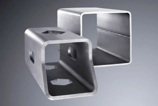
More importantly, laser cutting enables precise placement of risers and runners through programming ——. Even when dealing with irregular shapes (such as circular, square, or irregular forms), the system can automatically generate cutting paths by importing CAD drawings. This eliminates the "cutting deviation" issue caused by manual positioning, making it particularly suitable for batch processing of castings like automotive engine blocks and transmission housings.
2. Edge and burr removal: micron precision to improve surface quality
Castings often develop flash at mold closure points (typically 0.5-2mm thick), while burrs may accumulate on inner walls or cavity areas. If left unaddressed, these defects can compromise assembly precision – for instance, flash in bearing positions may cause installation jams. Traditional manual polishing methods prove inefficient (requiring 5-10 minutes per piece) and prone to two issues: over-polishing (resulting in oversized castings) or under-polishing (leaving residual micro-burrs).
The "precision cutting" advantage of laser cutting is particularly evident in this context: For flat flash, the "superficial cutting" mode can be employed (where the laser focus is concentrated at the top of the flash, with cutting depth limited to the flash thickness), which removes flash in one operation without damaging the main casting body. For hole positions or inner wall burrs (such as 10mm diameter casting holes), a small laser cutting head (diameter ≤5mm) can be used to penetrate the hole and cut along the burr edges. This method achieves a burr removal precision of 0.05mm and surface roughness Ra ≤3.2μm, fully meeting the surface requirements for precision assembly.
For example, the hydraulic valve block castings (made of aluminum alloy) processed by a construction machinery manufacturer are prone to burrs in the internal oil circuit holes (diameter 8mm). Traditional grinding can not reach the hole deeply. However, after removing the burrs through laser cutting, the flow efficiency of the oil circuit holes is increased by 15%, and the risk of oil circuit blockage caused by burr shedding is avoided.
Correction of key dimensions of castings: laser cutting makes up for "blunt error" and improves the pass rate
During the casting process, factors such as mold deformation and cooling shrinkage may cause dimensional deviations in castings (e.g., length deviation ±2mm or hole diameter deviation ±1mm). When these deviations exceed tolerance limits, traditional methods would scrap the casting, resulting in material waste. Laser cutting, however, can precisely remove excess material to correct critical dimensions, transforming defective blanks into qualified components, thereby significantly improving casting yield rates.
1. Plane size correction: accurately "trim" and restore the design size
For flat casting components (e.g., machine tool worktable castings, equipment base castings), when the original dimensions of the blank exceed standard specifications (e.g., design size 1000mm×500mm versus actual dimensions 1002mm×501mm), traditional milling processes require multiple setups and calibrations. These operations are prone to dimensional deviations caused by mechanical stress during machining. In contrast, laser cutting enables direct surface positioning for cutting paths, eliminating material allowances in one pass (2mm length allowance and 1mm width allowance). This precision method controls dimensional tolerances within ±0.1mm while completely avoiding clamping-induced deformation risks.
Consider a machine tool factory producing cast iron worktable components (dimensions: 2000mm×1000mm, thickness 30mm). The original casting exhibited length deviation of 1.8mm due to uneven cooling shrinkage. After laser trimming, the dimensions were precisely restored to 2000mm with surface flatness error ≤0.3mm/m² – fully meeting high-precision machine tool assembly requirements. This process prevented scrapping over 20 defective castings (each costing over 5000 yuan), effectively avoiding significant production losses.
2. Correction of hole position and slot position: accurate expansion of hole/slot to meet assembly requirements
The installation holes and positioning grooves of castings are critical assembly components. When deviations occur in the design hole positions (e.g., a 100mm center distance with an actual offset of 0.8mm) or when the hole diameter is undersized (e.g., a 20mm design diameter with an actual 19.5mm), traditional manufacturing processes require correction through boring or milling. However, boring may compromise the wall precision of the casting, while milling could potentially damage the original structural integrity of the component.
Laser cutting can be precisely corrected through two methods: First, "hole enlargement correction" — for holes with smaller diameters, the laser cuts along the outer edge of the original hole wall to expand it to the designed size (e.g., 19.5mm 20mm), ensuring the hole wall's circularity error is ≤0.05mm after expansion. Second, "hole position offset correction" — if the hole position is off-center, the laser first removes excess metal from the original hole position, then re-cut a new hole according to the designed coordinates, ensuring the center distance error is ≤0.1mm.
For example, a gearbox housing casting (made of ductile iron) produced by an automotive parts manufacturer encountered a design issue: the input shaft bore (originally designed with a 50mm diameter) showed a 0.6mm positional deviation due to mold misalignment. Through laser cutting for hole enlargement and positional correction, the bore diameter was precisely achieved at 50mm while maintaining positional deviation within 0.08mm. This successful transformation converted 30 defective housings into qualified products, recovering losses exceeding 100,000 yuan.
Complex casting structure processing: laser cutting breaks through the "traditional process limitations" to achieve flexible manufacturing
The intricate structures of castings (such as irregular hollowing, multi-stage steps, and inclined surfaces) pose significant challenges for traditional machining methods. While conventional milling struggles with deep cavity hollowing and stamping requires custom molds (which are costly and time-consuming), laser cutting's "flexibility" allows direct processing of complex structures on castings without additional tooling. This breakthrough dramatically expands the design possibilities and application scope of castings.
1. Anisotropic hollowing: no need to open the mold, restore complex design
Some castings (such as decorative cast iron parts and heat dissipation aluminum alloy castings) need to be designed with irregular hollow structures (such as patterns, grids, and irregular holes). In traditional processes, such structures need to be carved on the mold. If the design is modified, the mold needs to be remade, which is costly and time-consuming (the mold making cycle is usually 15-30 days).
Laser cutting enables direct fabrication of irregular hollow patterns on casting blanks: By importing the designed hollow pattern into CAD software to generate cutting paths, the laser can precisely follow these paths. Even complex curved hollows (such as 5mm radius arcs and 0.5mm wide slits) can be accurately machined. Taking an aluminum alloy heat dissipation casting (300mm×200mm, 10mm thick) as an example, laser cutting can create dense heat dissipation holes (3mm diameter, 5mm spacing) on the casting surface. With a cutting speed of 0.5m/min, the hollowed casting achieves a 20% weight reduction and a 25% improvement in heat dissipation efficiency.
More importantly, the "no-mold" feature of laser cutting supports rapid design iterations —— If customers need to adjust the hollow pattern, they only need to modify the CAD drawing, and the program can be reprogrammed and processing started within 1 hour, without waiting for mold production. This is particularly suitable for customized casting processing (such as special castings for niche equipment and quick prototyping of sample parts).
2. Multi-stage steps and inclined surface processing: precise depth control, suitable assembly gap
Certain castings (e.g., hydraulic cylinder barrels and precision valve bodies) require machining of multi-stage steps (cylindrical surfaces with varying diameters) or inclined surfaces (such as sealing surfaces with 15° and 30° angles). Traditional turning processes for steps often require multiple tool height adjustments, leading to uneven end faces. When machining inclined surfaces, specialized angle tools are needed, which significantly increases production costs.
Laser cutting utilizes "dynamic focusing" technology to precisely control cutting depth and angles, enabling the processing of multi-stage steps and inclined surfaces. When creating steps, the laser follows coordinate paths with varying diameters, achieving a depth error ≤0.05mm per segment and verticality error ≤0.1° on step edges. For inclined surfaces, the laser cutting head tilts at preset angles (adjustable from 0° to 90°), directly producing surfaces with surface roughness Ra ≤1.6μm that meet sealing requirements without requiring additional polishing.
For example, a hydraulic equipment manufacturer processes cylinder barrel castings (made of 20# steel with an inner diameter of 100mm) that require three stepped sections on the inner wall (diameter 95mm, 90mm, 85mm respectively, each 50mm long). After laser cutting, the diameter error of each step section must be ≤0.08mm, and the perpendicularity error between the step end face and the cylinder barrel axis must be ≤0.05°, fully meeting the assembly clearance requirements for piston sealing (0.1-0.2mm).
Adaptation precautions of casting and laser cutting: material, thickness and process matching
Although laser cutting has significant advantages in casting processing, not all castings are suitable for laser cutting. It is necessary to select appropriate laser type and process parameters according to the material and thickness of castings to avoid problems such as "low cutting efficiency" and "poor surface quality".
1. Material adaptation: Different laser types are selected for different casting materials
- Cast iron castings (gray cast iron, ductile cast iron): this kind of material has high hardness (HB180-250), but it is brittle. It is recommended to use optical fiber laser cutting (power 6000W-12000W), and combine with high pressure nitrogen (to avoid oxidation of cutting surface) during cutting. The upper limit of cutting thickness can reach 80mm;
- Aluminum alloy casting: aluminum alloy has high reflectivity (about 90%), which is easy to reflect laser energy. It is recommended to use "green laser cutting" (wavelength 532nm, absorption rate is 3 times higher than that of fiber laser), or add "absorption coating" (black absorbent spraying) during fiber laser cutting, and the upper limit of cutting thickness can reach 50mm;
- Stainless steel casting: Stainless steel has high high temperature strength and poor thermal conductivity. It is recommended to use optical fiber laser cutting (power 3000W-6000W) and high pressure oxygen (to help combustion and improve cutting speed). The upper limit of cutting thickness can reach 60mm.
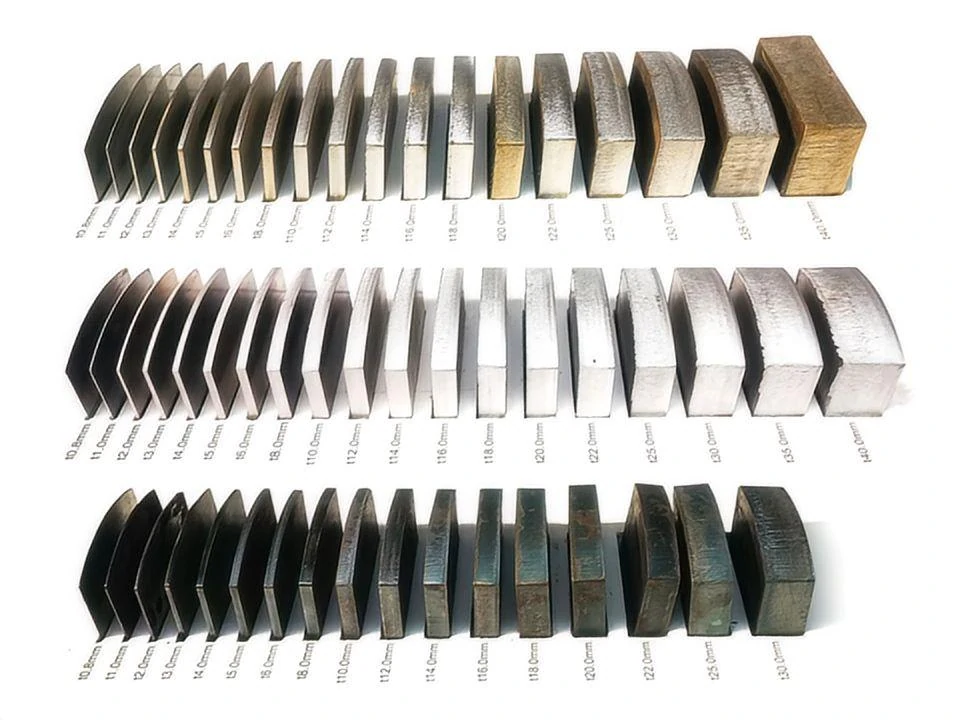
2. Thickness adaptation: different thickness requires adjustment of process parameters
- Thin castings (thickness ≤10mm): suitable for high speed and low power cutting (such as 3000W fiber laser, cutting speed 1-2m/min), to avoid excessive power leading to casting melting deformation;
- Medium and thick castings (thickness 10-50mm): it is necessary to balance the speed and power (such as 6000W fiber laser, cutting speed 0.3-0.8m/min), and increase the auxiliary gas pressure (0.8-1.2MPa) to ensure that the slag is fully blown away;
- Thick castings (thickness> 50mm): high power laser (above 10,00W), low speed cutting (0.1-0.3m/min), and "layer cutting" mode (cut the surface first, then gradually deep) should be used to avoid insufficient laser energy to cut through.
epilogue
The integration of laser cutting with casting processes not only addresses the longstanding challenges of traditional methods—such as low precision, significant deformation, and poor efficiency—but also expands the design and application boundaries —— of castings. From batch casting pretreatment to dimensional correction of defective blanks, and even flexible machining of complex structures, laser cutting delivers precise and efficient solutions. For professionals in casting manufacturing and processing, understanding the suitable application scenarios and process logic of laser cutting enables better selection of processing methods, thereby enhancing both product quality and production efficiency.
If you have any questions about "laser cutting parameters for castings with different materials" and "laser processing solutions for complex castings", please leave a comment in the comment section. We will continue to share more popular science knowledge related to castings and laser cutting!