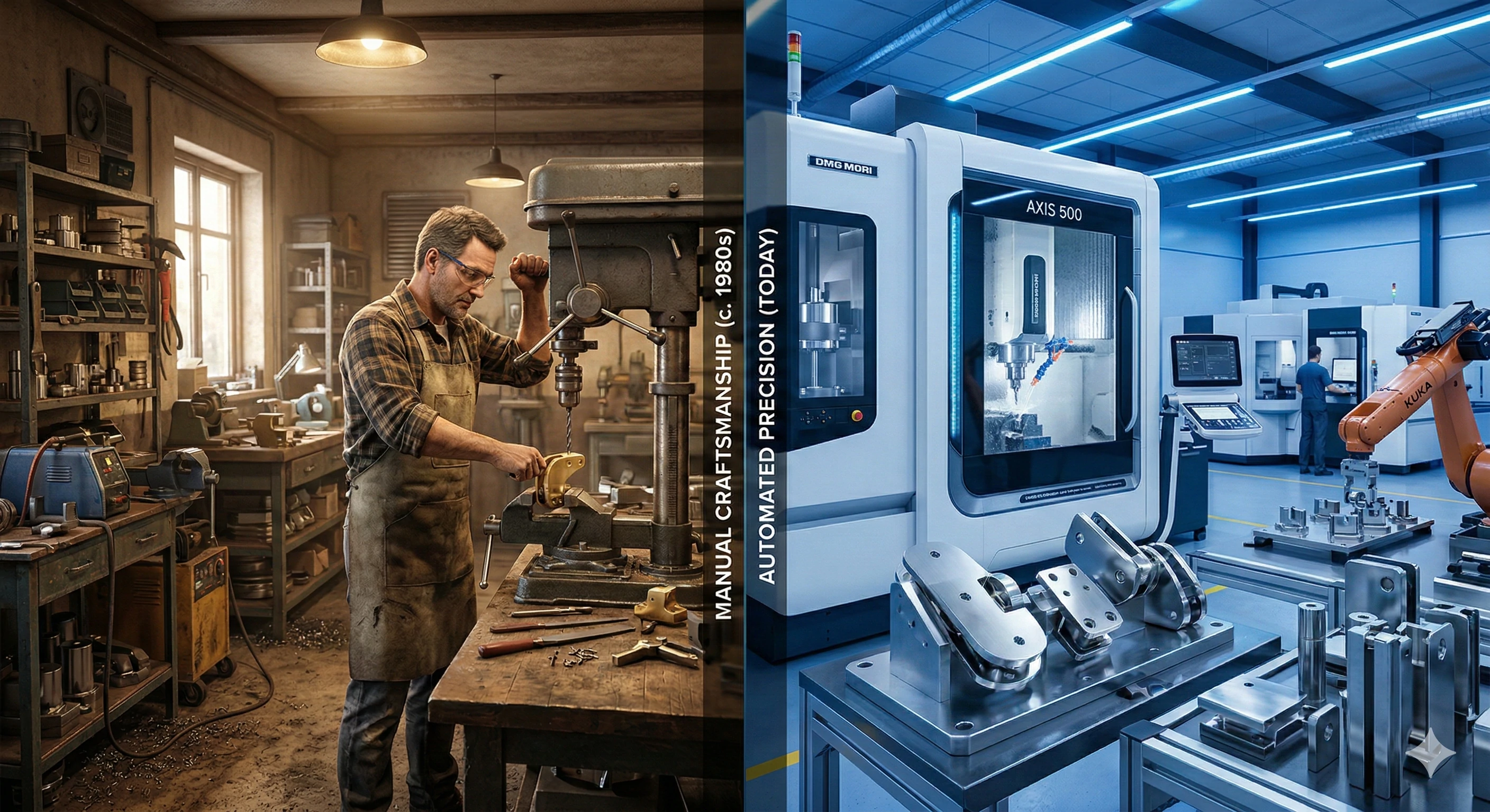
machines are the "precision brains" of modern manufacturing. They automate tool control via programming to achieve micron-level precision machining. In our factory, a raw casting—such as a glass spigot base—must undergo CNC drilling, milling, and other processes to become a finished hardware component that meets installation requirements. This blog breaks down the 7 core components of CNC machines, revealing how the "brain" directs the "muscles" to achieve precision manufacturing with a tolerance of 0.01mm.
Input Device: The Machine’s "Command Transmitter"
The input device serves as the communication bridge between humans and the machine, with the core function of transmitting machining instructions to the CNC system.
• Common Types: USB drives, Ethernet cables, or direct integration with computers.
• Core Data: Loads (the programming language for CNC machines) generated by CAD/CAM software. This code contains all machining information, including toolpaths, cutting speeds, and tool selection.
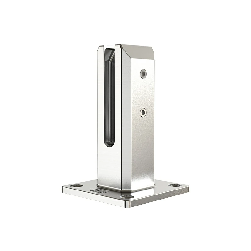
• Practical Application: When machining the base holes of glass spigots, we import customized G-code into the machine via a USB drive to ensure the hole position and diameter fully meet design specifications.
Machine Control Unit (MCU): The Machine’s "Brain"
The is the core of the entire CNC system, acting as the "command center" that interprets instructions and issues operational commands.
Core Components
• Data Processing Unit (DPU): Decodes machining information in G-code, converting complex design drawings into digital signals recognizable by the machine.
• Control Loop Unit (CLU): Sends precise control instructions (e.g., speed, position) to the drive system based on decoded information.
Key Value: An MCU with high computing speed can accurately handle complex surface machining. For example, when producing impeller parts, their intricate spiral structures rely on the MCU’s efficient computing to ensure surface smoothness and dimensional accuracy.
Machine Spindle/Tool Magazine: The Machine’s "Executive Hands"
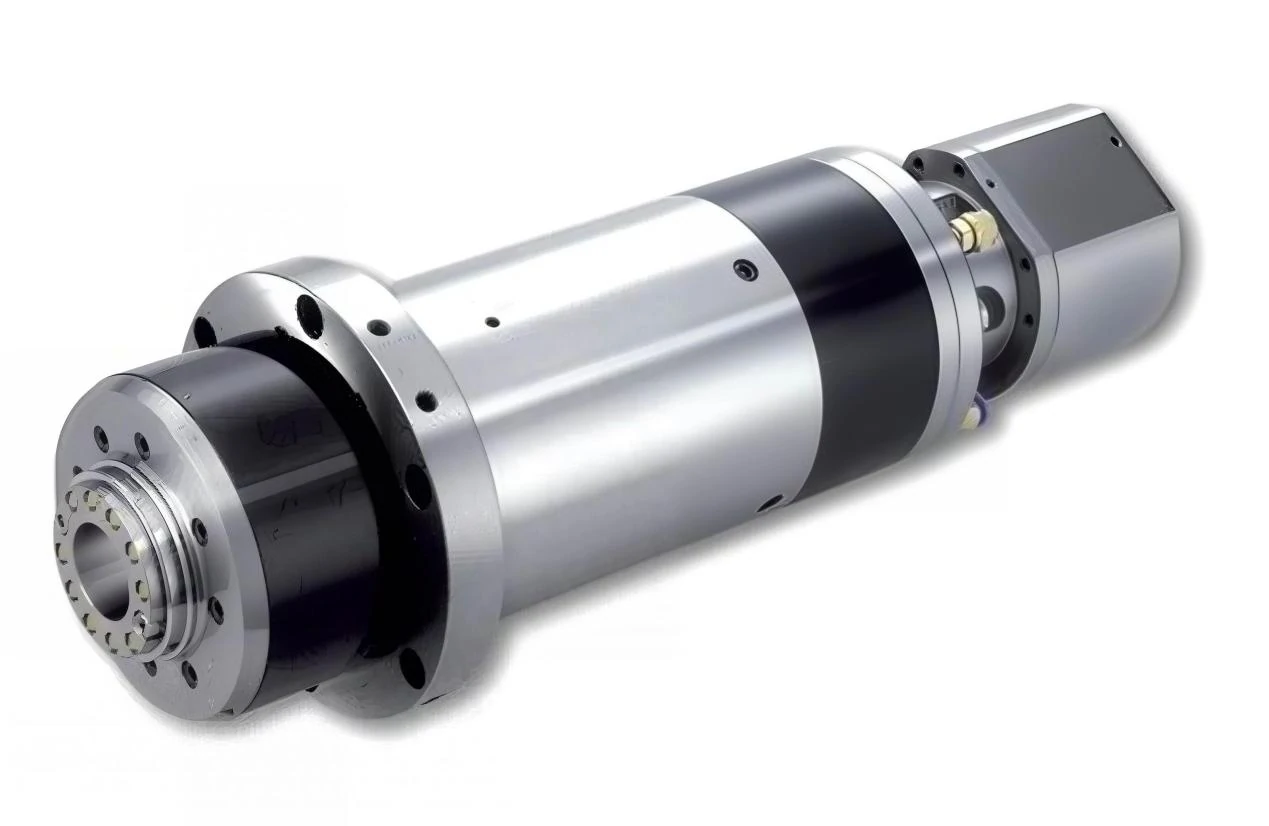
These are the core components that directly perform cutting operations, equivalent to the machine’s "hands," responsible for contacting and machining workpieces.
• Spindle Function: Drives cutting tools (drills, end mills, etc.) to rotate at extremely high speeds (e.g., 10,000 revolutions per minute) to achieve drilling, milling, cutting, and other machining actions.
• Automatic Tool Changer (ATC): A core configuration of modern CNC machines. It automatically switches between different tools, completing multiple processes (drilling, tapping, face machining) without manual intervention, significantly improving .
• Practical Application: When machining glass spigots made of , the spindle drives a special end mill to flatten the surface, then automatically switches to a drill for hole machining—all in one seamless operation.
Drive System: The Machine’s "Power Muscles"
The drive system is the power source of the machine, responsible for moving the worktable and spindle along the X, Y, and Z axes to achieve precise positional movement.
Core Components
• Motor: Divided into (preferred for high precision) and stepper motors. Servo motors feature feedback functions for higher positioning accuracy.
• Ball Screw: Converts the motor’s rotational motion into linear motion. Its machining accuracy directly determines the machine’s positioning precision, making it a key component for ensuring machining tolerances.
Factory Standard: We use high-torque servo motors. Even when machining high-strength stainless steel like duplex steel 2205, they provide stable power to avoid precision deviations caused by insufficient power during cutting.
Feedback System: The Machine’s "Sensory Nerves"
The feedback system acts as the machine’s "nerve endings," responsible for real-time monitoring of machining status and feeding data back to the MCU to achieve closed-loop control.
• Working Principle: Uses components such as or encoders to collect real-time data on the tool’s actual position and speed, with an accuracy of up to 0.001mm.
• Core Function: If the tool position deviates slightly, the feedback system immediately sends a signal to the MCU, which quickly adjusts the drive system to correct the deviation.
• Key Value: This is the core of CNC machines’ "self-calibration" capability and the reason for their far superior machining accuracy compared to conventional machines. For example, when machining parts with a hole diameter tolerance of ±0.01mm, the feedback system monitors the process throughout to ensure each hole is precise.
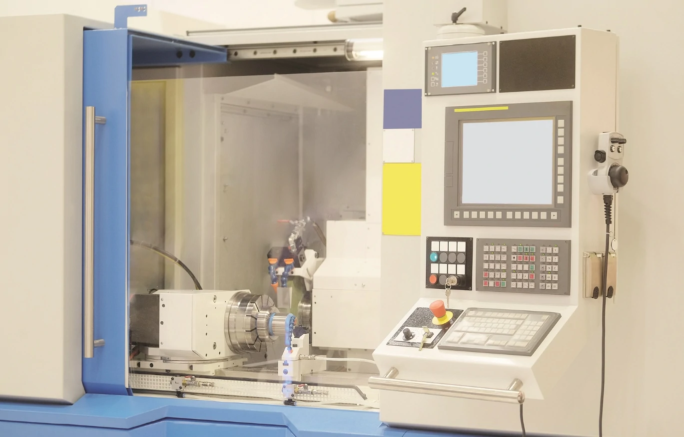
Display Unit/Control Panel: The Machine’s "Interface"
This is the direct interaction platform between operators and the machine, equivalent to the machine’s "face," responsible for operation control and status monitoring.
• Core Functions: Real-time display of current machining coordinates, spindle speed, tool number, machining progress, and other information via the screen. It also features an operation keyboard for operators to input instructions and adjust parameters.
• Practical Design: Equipped with a fault alarm function. If issues such as or program errors occur during machining, error messages are displayed immediately, allowing operators to handle problems promptly and avoid batch scrap.
Bed/Frame: The Machine’s "Support Skeleton"
The bed and frame form the basic support structure of the CNC machine, equivalent to the "skeleton," bearing all core components. Their stability directly affects machining accuracy.
• Material Characteristics: Usually made of heavy , offering high weight and rigidity.
• Core Advantage: The heavy bed effectively absorbs vibrations generated during machining—vibrations are the "natural enemy" of precision machining. When machining hard metals, vibrations can cause "chatter marks" on the workpiece surface, affecting smoothness.
• Practical Impact: When machining stainless steel parts, our heavy-duty bed ensures stable machine operation, ultimately achieving mirror-level surface precision for workpieces.
Why Should Casting Buyers Care About In-House CNC Machining Capabilities?
For casting buyers, CNC machining capabilities are a key measure of a supplier’s strength—and this is our core advantage:
• Industry Status Quo: Many foundries only provide raw castings. Buyers must find separate processing factories for finishing (drilling, milling, etc.), which not only increases communication costs but also risks product disqualification due to inconsistent quality standards between different manufacturers.
• Our Advantage: As an integrated factory, we offer one-stop "casting + CNC finishing" services. After casting formation, workpieces are directly transferred to our in-house CNC workshop for machining.
• Purchasing Value: Single-supplier coordination ensures unified quality standards, eliminating concerns about coordination between casting and machining processes. It also reduces intermediate links, lowering procurement costs and lead times.
Frequently Asked Questions (FAQ)
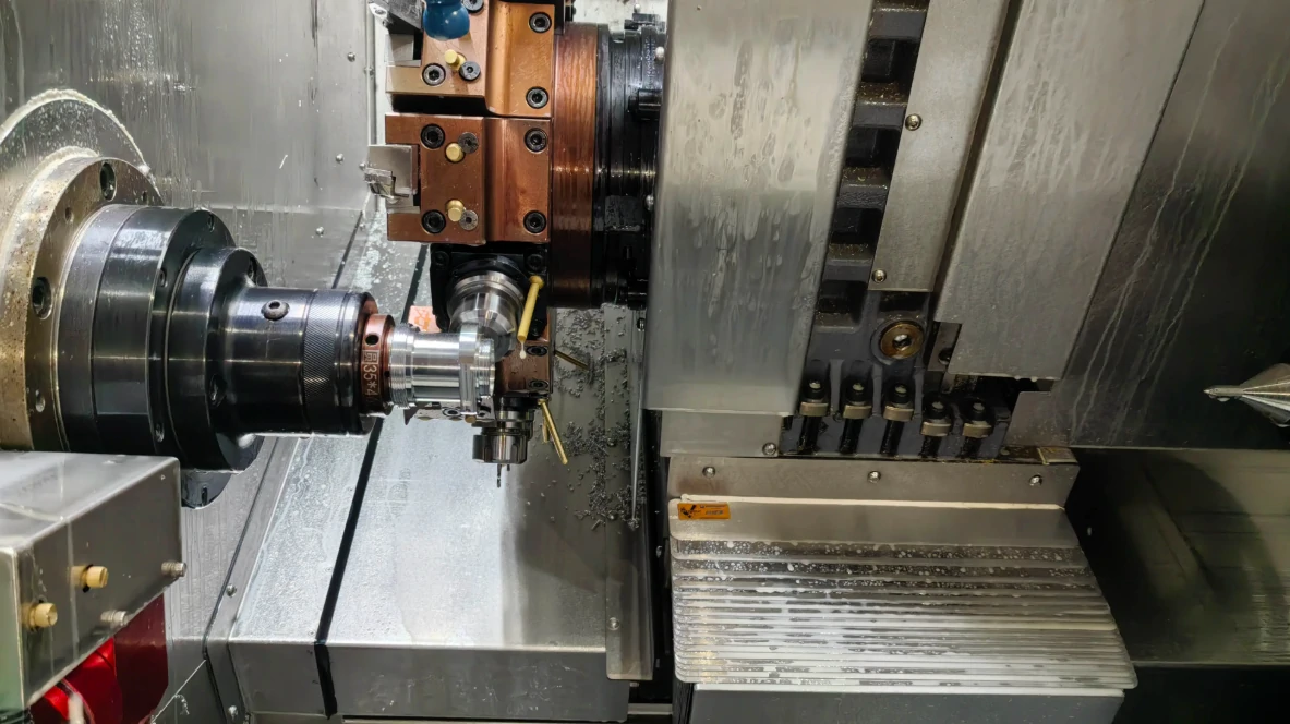
1. What is the difference between CNC turning and CNC milling?
CNC milling involves rotating tools and fixed workpieces, suitable for machining square and irregular parts (e.g., glass spigot bases). CNC turning involves rotating workpieces and fixed tools, suitable for machining cylindrical parts (e.g., pump shafts, cylindrical hardware components).
2. Why choose servo motors over stepper motors?
Servo motors have feedback loops, enabling real-time sensing of their position and speed to accurately respond to control instructions. Stepper motors lack feedback, moving only in fixed steps and prone to step loss deviations. For industrial precision machining, servo motors are a core configuration for ensuring accuracy.
3. What is G-code?
G-code is the standard programming language for CNC machines. Through a series of code instructions, it tells the machine "where to go, how fast to move, how deep to cut, and which tool to use"—serving as the key bridge between design drawings and actual machining.
Conclusion
with CNC machines is a "symphony" of coordinated work among 7 core components—from instruction transmission via the input device, precise command from the MCU, to efficient execution by the drive system and spindle. Every link is indispensable. Only when all components work perfectly together can 0.01mm-level tolerance control be achieved, producing precision parts that meet high-end hardware requirements.
If you need precision hardware with one-stop "casting + finishing" services, no need to coordinate multiple suppliers. Our OEM team can provide "ready-to-install" turnkey solutions for you.
Footnotes
1. Comprehensive overview of CNC history and mechanics.
2. Detailed explanation of G-code programming commands.
3. Technical definition of Machine Control Units.
4. Strategies for optimizing production speed and quality.
5. Material properties and applications of Duplex 2205.
6. Engineering principles behind servo motor operation.
7. How linear encoders ensure positional accuracy.
8. Causes and effects of tool degradation in machining.
9. Properties making cast iron ideal for machine beds.