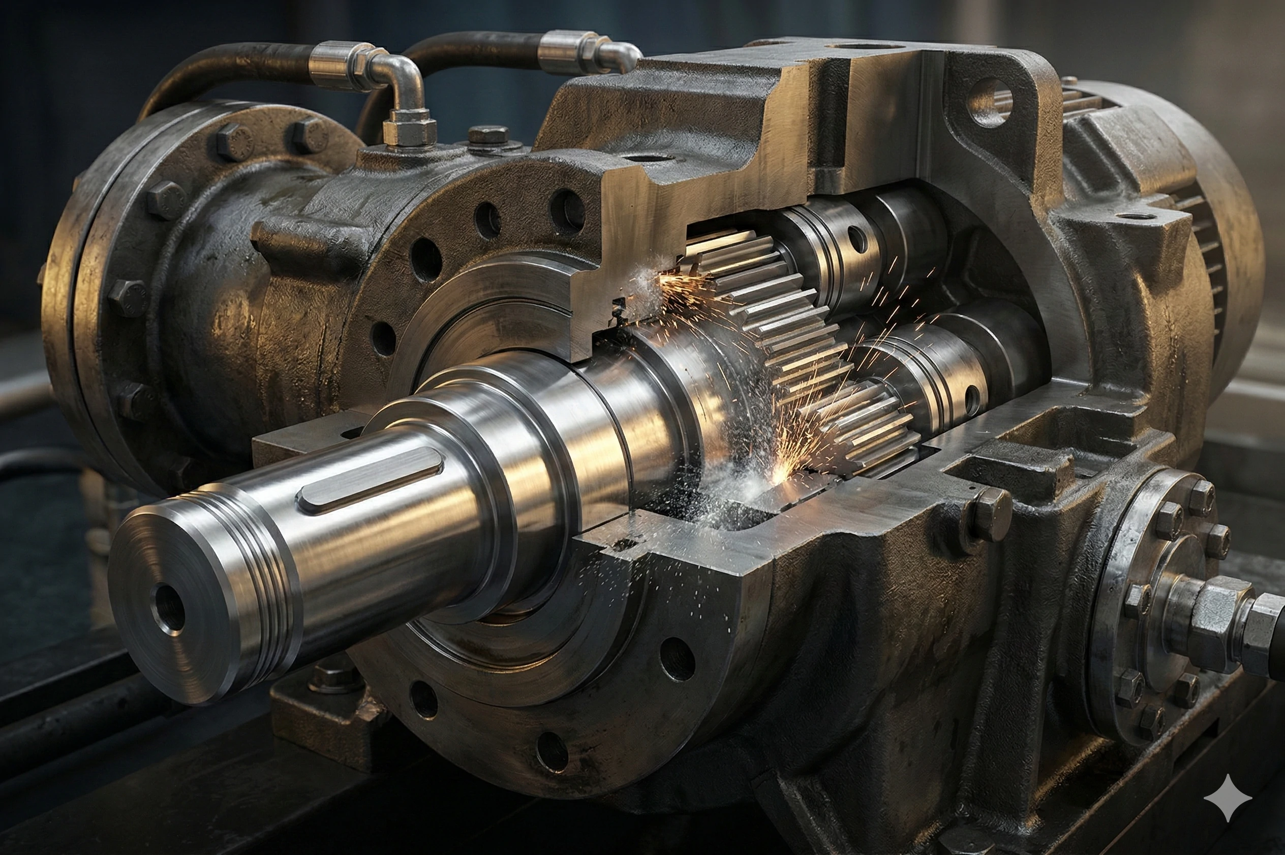
When our factory produces , we see firsthand how a single failed component halts entire production lines. You might struggle with equipment downtime caused by sheared or vibrating shafts, leading to massive financial losses. We engineer custom precision shafts to ensure your machinery operates flawlessly under heavy loads. Shafts are the unsung heroes of the industrial world, transferring power and motion to drive massive hydraulic pumps or articulate robotic arms.
Machined shafts manufacturing is the precise CNC process of shaping raw metal bars into custom rotary components. It involves turning, milling, and grinding to create specific features like bearing journals and keyways, ensuring exact tolerances for optimal mechanical power transmission.
Let us explore the critical steps and behind producing these vital industrial components. This guide breaks down the manufacturing process, the critical materials used, and why micron-level precision is mandatory to prevent mechanical failure.
What is the Anatomy of a Custom Machined Shaft?
Have you ever received a replacement shaft only to find the bearings will not fit? In our , we constantly help clients overcome this frustration by focusing on precise geometric details. A shaft is never just a simple round bar; it requires exact engineering to function correctly.
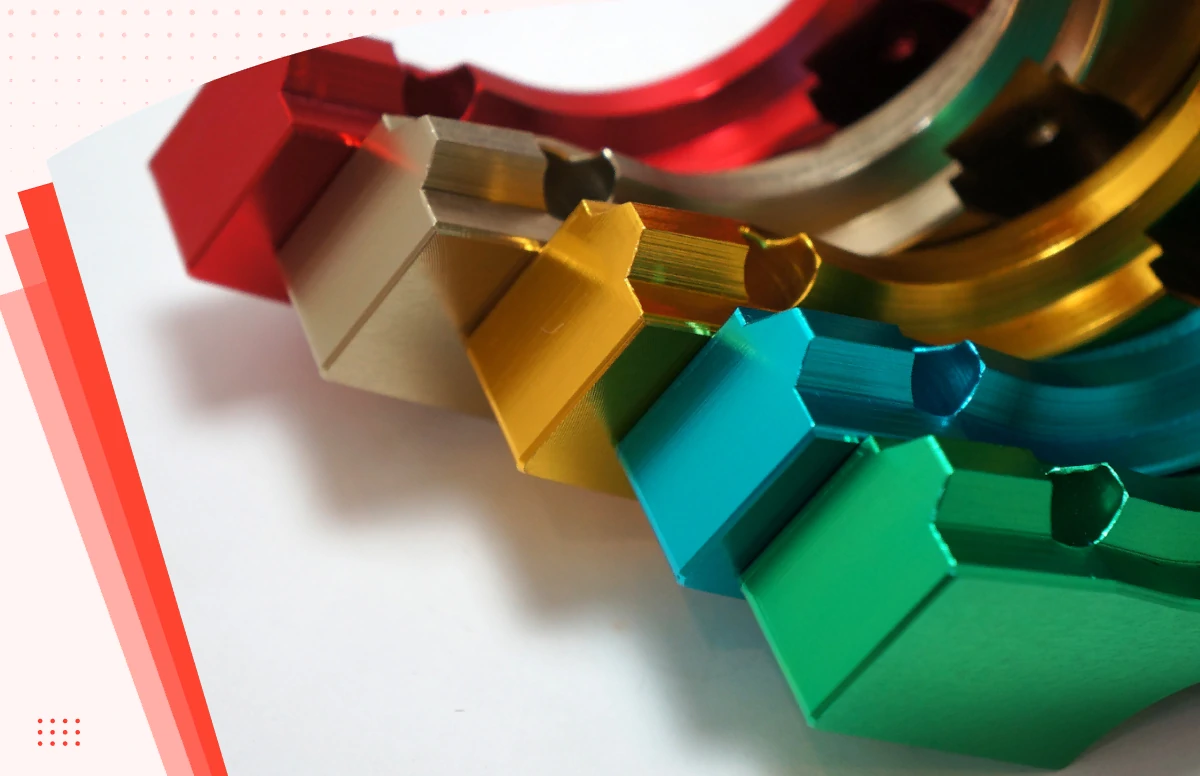
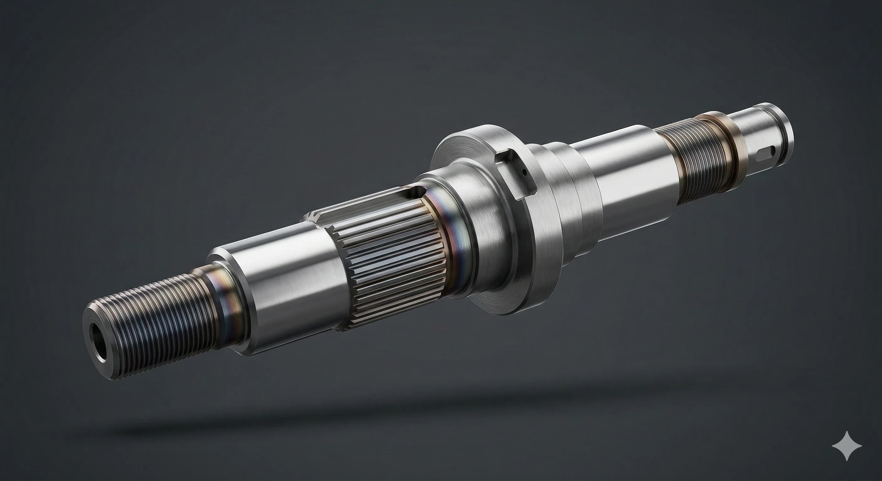
The anatomy of a custom machined shaft consists of highly complex engineered geometries, including ultra-smooth bearing journals, milled keyways, splines for torque transmission, threaded sections for locknuts, and specific chamfers to prevent stress fractures under heavy operational loads.
Key Features We Machine
When we analyze technical drawings, we focus on specific functional zones. Bearing journals are critical features. A bearing journal is a specific section of the shaft that is machined and often ground to an incredibly . It is the exact location where the bearing will sit. If we machine the journal too small, the shaft will rattle inside the bearing. If we make it too large, the bearing will not press on. We also machine threads for securing locknuts and retaining rings.
Power Transmission Elements
To transmit torque efficiently, shafts require keyways and splines. A keyway is a slot milled into the shaft that matches a slot in a mating component, like a gear, pulley, or . A small piece of metal, called the key, is inserted into this slot. This locks the two pieces together so they rotate simultaneously without slipping.
Stress Reduction Techniques
Sharp corners invite mechanical failure. We always machine chamfers and radii to eliminate sharp 90-degree internal corners. This prevents under heavy loads, ensuring the longevity of your equipment.
| Feature | Primary Function | Manufacturing Method |
|---|---|---|
| Bearing Journals | Provide a tight-tolerance seat for bearings | Turning and Cylindrical Grinding |
| Keyways & Splines | Lock mating components to transmit torque | CNC Milling |
| Threads | Secure locknuts and retaining rings | CNC Turning |
| Chamfers & Radii | Prevent stress fractures by eliminating 90-degree corners | CNC Turning / Milling |
How Does the Manufacturing Process Work from Turning to Grinding?
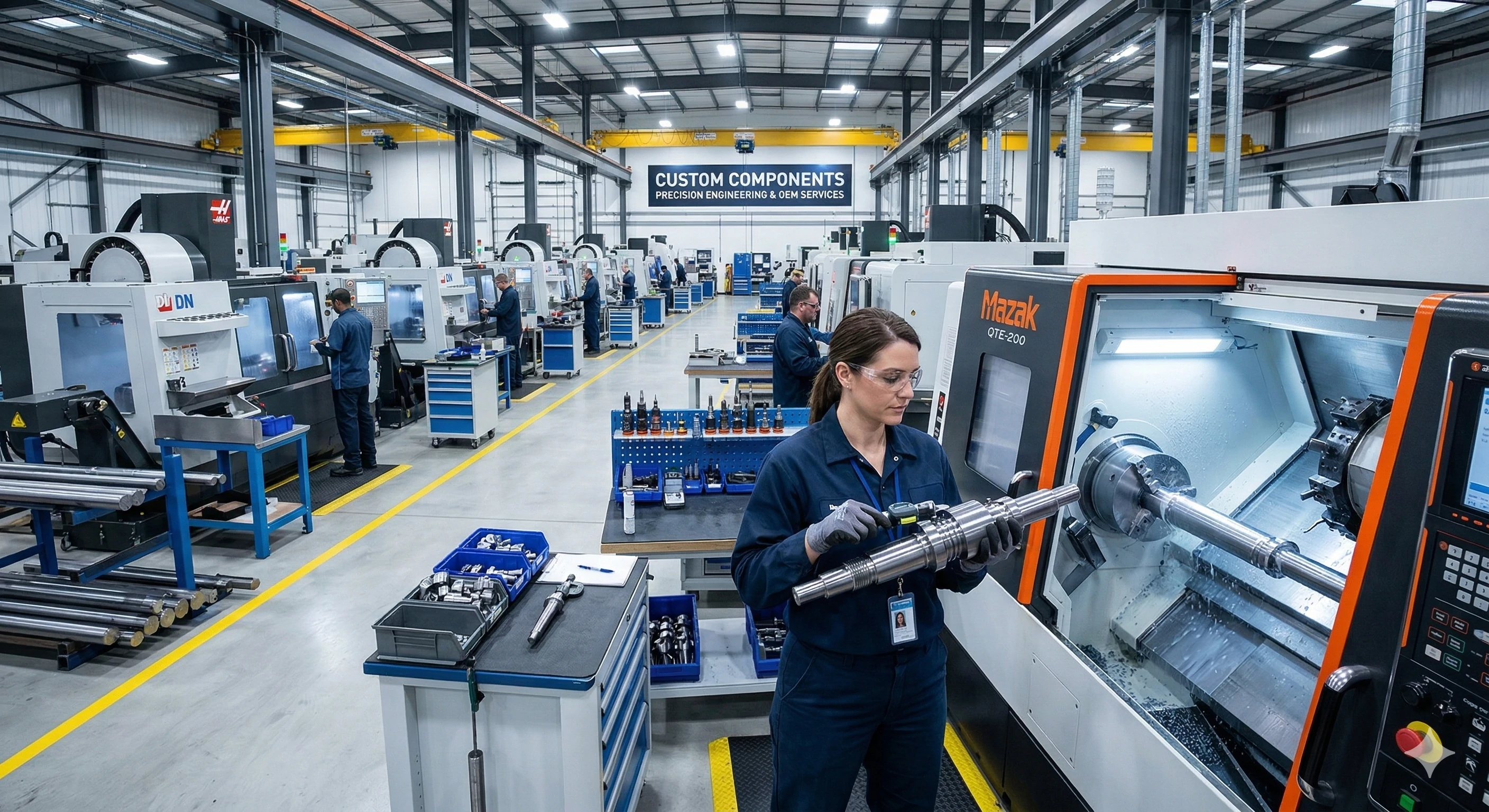
Walking through our factory floor, the noise of metal cutting metal is constant. You might worry about inconsistent batches ruining your final assembly. We solve this by utilizing a strict multi-step to guarantee every shaft meets exact specifications, showcasing our factory floor capabilities.
The manufacturing process for custom shafts involves CNC turning for rough shaping, CNC milling to cut keyways and cross-holes, specialized heat treatment for surface hardness, and final cylindrical grinding to achieve perfect microscopic tolerances for precise bearing fits.
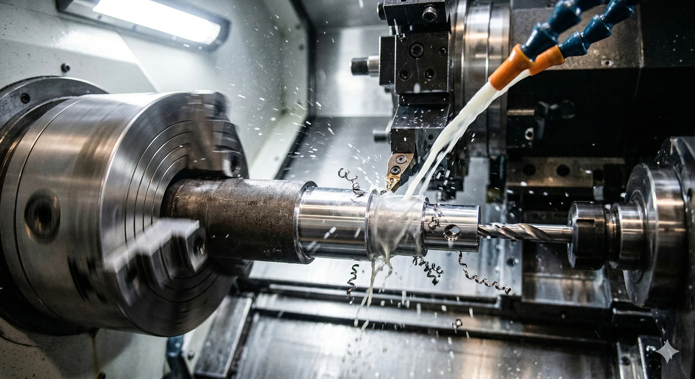
CNC Turning and Milling
The process begins with CNC turning for the rough and finish cuts. We load raw bar stock into a . The machine spins the metal while a stationary tool peels away material to create the stepped diameters and threads. Next, the turned shaft is moved to a Vertical Machining Center to cut the keyways, flats, and cross-holes. We can also perform these steps simultaneously on a Mill-Turn center.
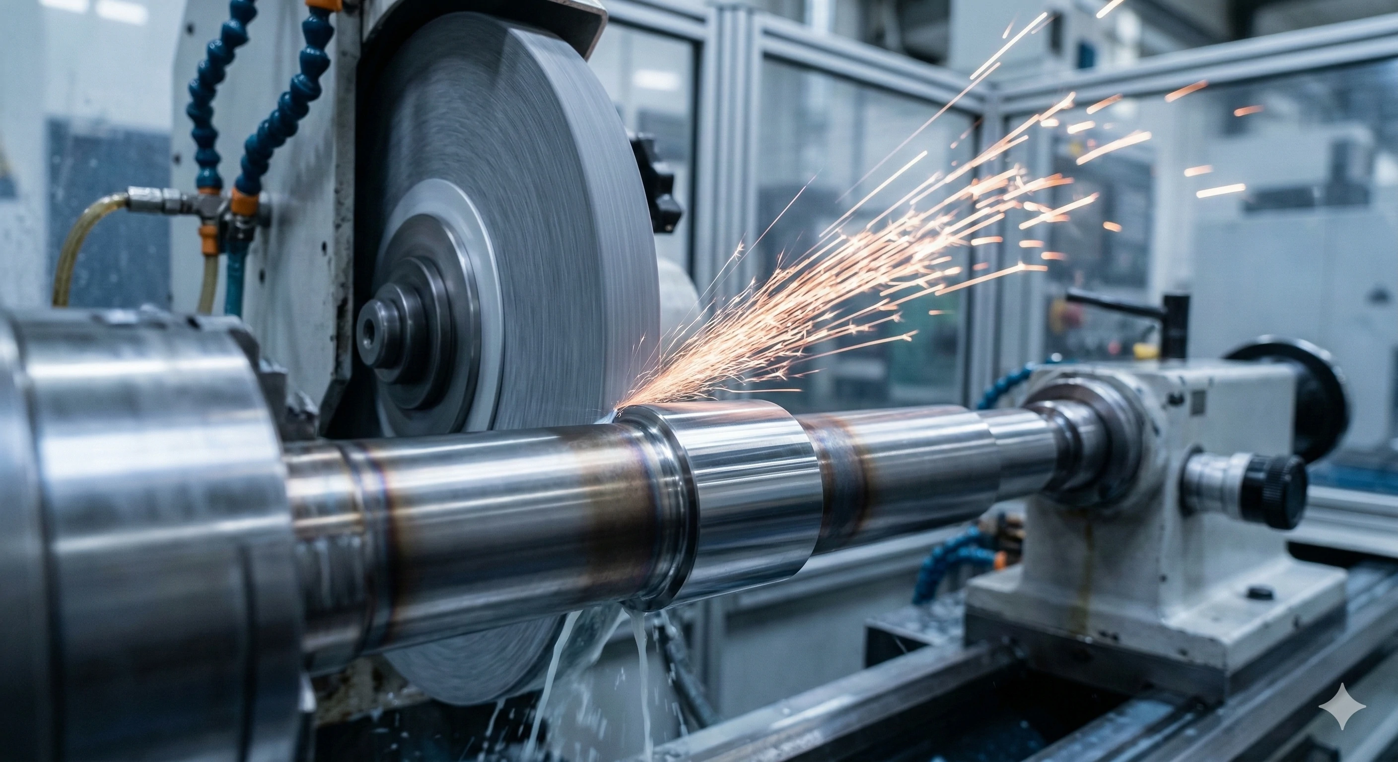
Heat Treatment and Final Grinding
Raw steel often needs enhancement for heavy industrial use. We apply heat treatment, such as , to make the outer surface highly wear-resistant. This keeps the core tough enough to absorb shock. Turning gets you close, but cylindrical grinding makes it perfect. A grinding wheel takes off the final microscopic layer of metal. This allows us to hit exact tolerances, such as +/- 0.005mm, for bearing fits.
Surface Finish Standards
The required surface finish depends on the application. We utilize different techniques to achieve the necessary smoothness.
| Application Area | Target Surface Finish (Ra) | Primary Process Used |
|---|---|---|
| Standard Shaft Sections | Ra 1.6 to 3.2 micrometers | CNC Turning |
| Bearing Journals | Ra 0.4 to 0.8 micrometers | Cylindrical Grinding |
| Seal Areas | Ra 0.4 to 0.8 micrometers | Cylindrical Grinding |
Why are "Runout" and Vibration the Enemy of the Shaft?
Nothing damages a brand reputation faster than a machine vibrating itself to pieces in the field. Our quality control engineers know that microscopic wobbles cause massive problems. We relentlessly test for runout to protect your and bearings from premature destruction, building B2B trust through deep engineering.
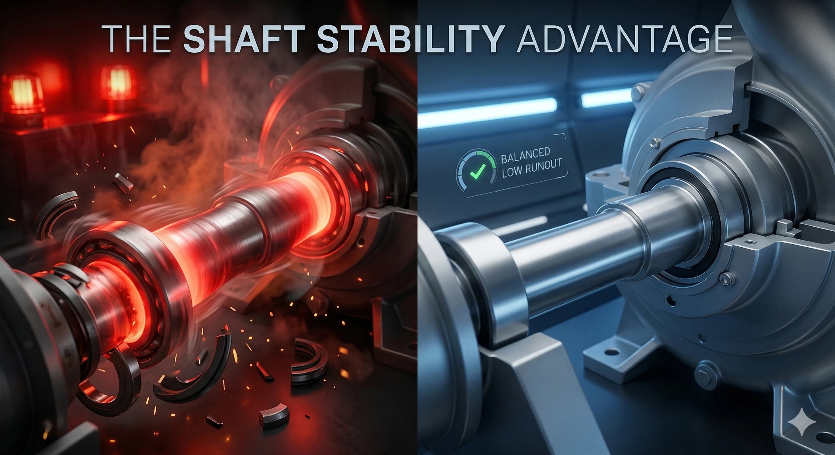
Runout is the amount a shaft wobbles off its true center axis during rotation. Even 0.05mm of runout on a high-speed shaft generates massive vibration, which destroys mechanical seals, overheats bearings, and ultimately causes catastrophic machine failure.
Understanding Runout Consequences
Runout is a critical factor we monitor closely. It is the amount a shaft wobbles off its true center axis as it rotates. When a pump shaft spins at 3,000 RPM, any deviation from the center is disastrous. If it has even 0.05mm of runout, it generates massive vibration. This vibration destroys the mechanical seals and overheats the bearings. Ultimately, this leads to catastrophic machine failure.
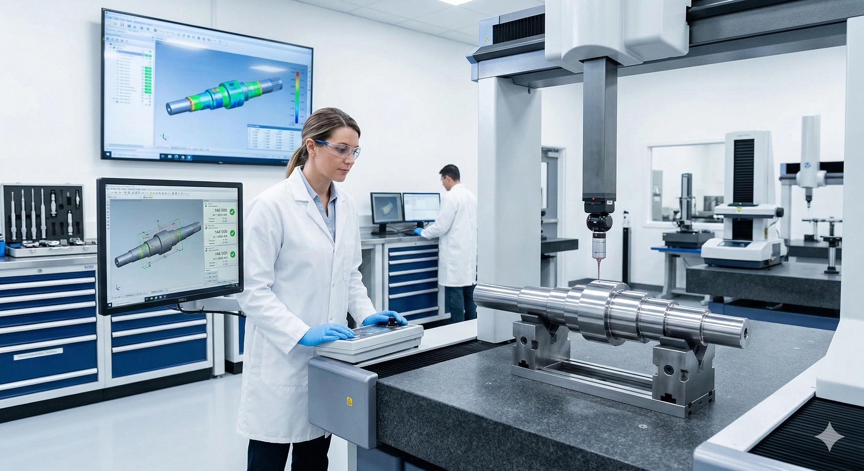
Our Strict Quality Control Measures
We do not leave precision to chance. Our quality control utilizes strict Coordinate Measuring Machines (CMM) and dial indicators to verify part geometry. We check for concentricity, straightness, and Total Indicator Runout (TIR) before any batch leaves the facility. An image of a shiny, newly machined steel shaft being measured by a precision dial indicator gauge communicates this quality control. Because we also cast pump housings and impellers, guaranteeing low-runout pump shafts creates a reliable entire pump assembly for our clients.
What is the Material Selection Matrix for OEM Shafts?
Choosing the wrong metal is a costly mistake we see too often. When we consult with clients, they frequently struggle with parts rusting or snapping under pressure. We guide you through the material selection process to balance strength, corrosion resistance, and overall cost-effectiveness.
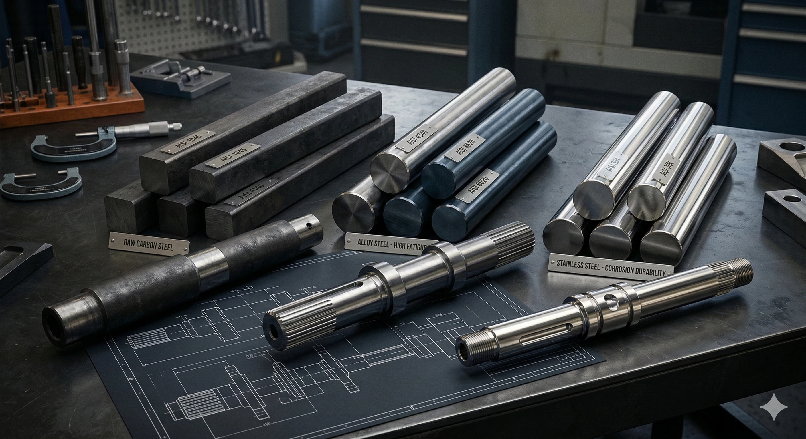
The material selection matrix for OEM shafts determines performance based on application needs. Carbon steel offers good machinability, alloy steel provides extreme fatigue resistance, and stainless steel delivers exceptional corrosion durability for harsh environments like marine or chemical applications.
Balancing Strength and Environment
Standard rotary stock is fine for a hobbyist, but OEM machinery requires specific alloy certifications. We help you select the exact material based on your specific operational environment. Carbon Steel, specifically 1045, is widely used in our production. It offers good machinability and is easy to induction harden. We commonly use it for general-purpose motors and conveyor rollers.
High-Performance Alloys
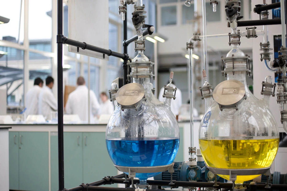
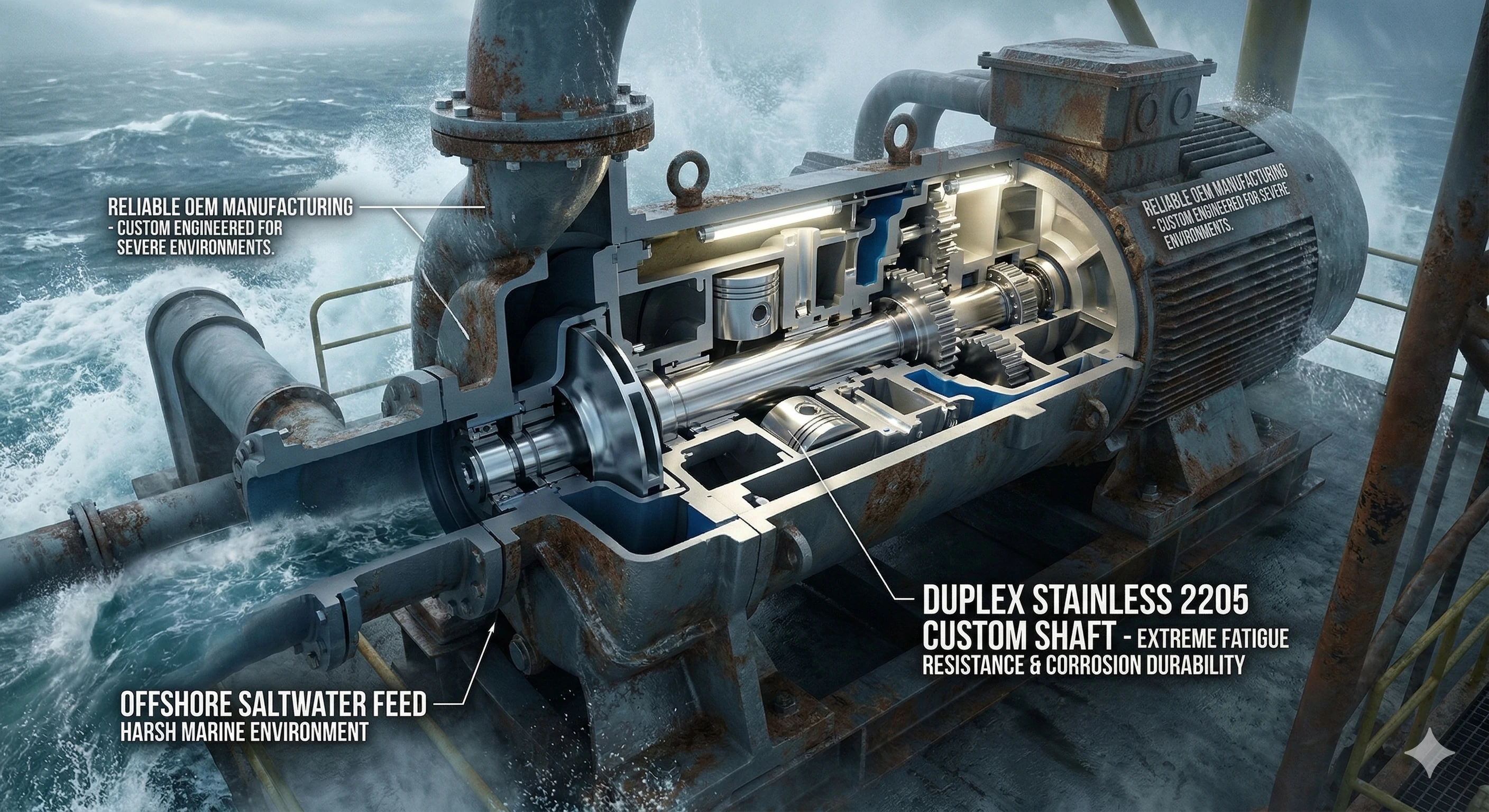
For heavy-duty applications, we turn to tougher alloys. Alloy Steel 4140 provides high tensile strength and extreme fatigue resistance, making it perfect for heavy-duty agricultural equipment and drive shafts. If the shaft operates in wet or corrosive environments, Stainless Steel 316 or 420 offers exceptional corrosion resistance and is highly durable. This is ideal for marine hardware, chemical pumps, and food-grade machinery. For the ultimate protection in extreme conditions, Duplex Stainless 2205 combines high strength with ultimate chloride resistance for offshore drilling equipment and saltwater desalination pumps.
| Material | Key Characteristics | Common Applications |
|---|---|---|
| Carbon Steel (1045) | Good machinability, easy to induction harden. | General-purpose motors, conveyor rollers. |
| Alloy Steel (4140) | High tensile strength and extreme fatigue resistance. | Heavy-duty agricultural equipment, drive shafts. |
| Stainless Steel (316/420) | Exceptional corrosion resistance, highly durable. | Marine hardware, chemical pumps, food-grade machinery. |
| Duplex Stainless (2205) | Combines high strength with ultimate chloride resistance. | Offshore drilling equipment, saltwater desalination pumps. |
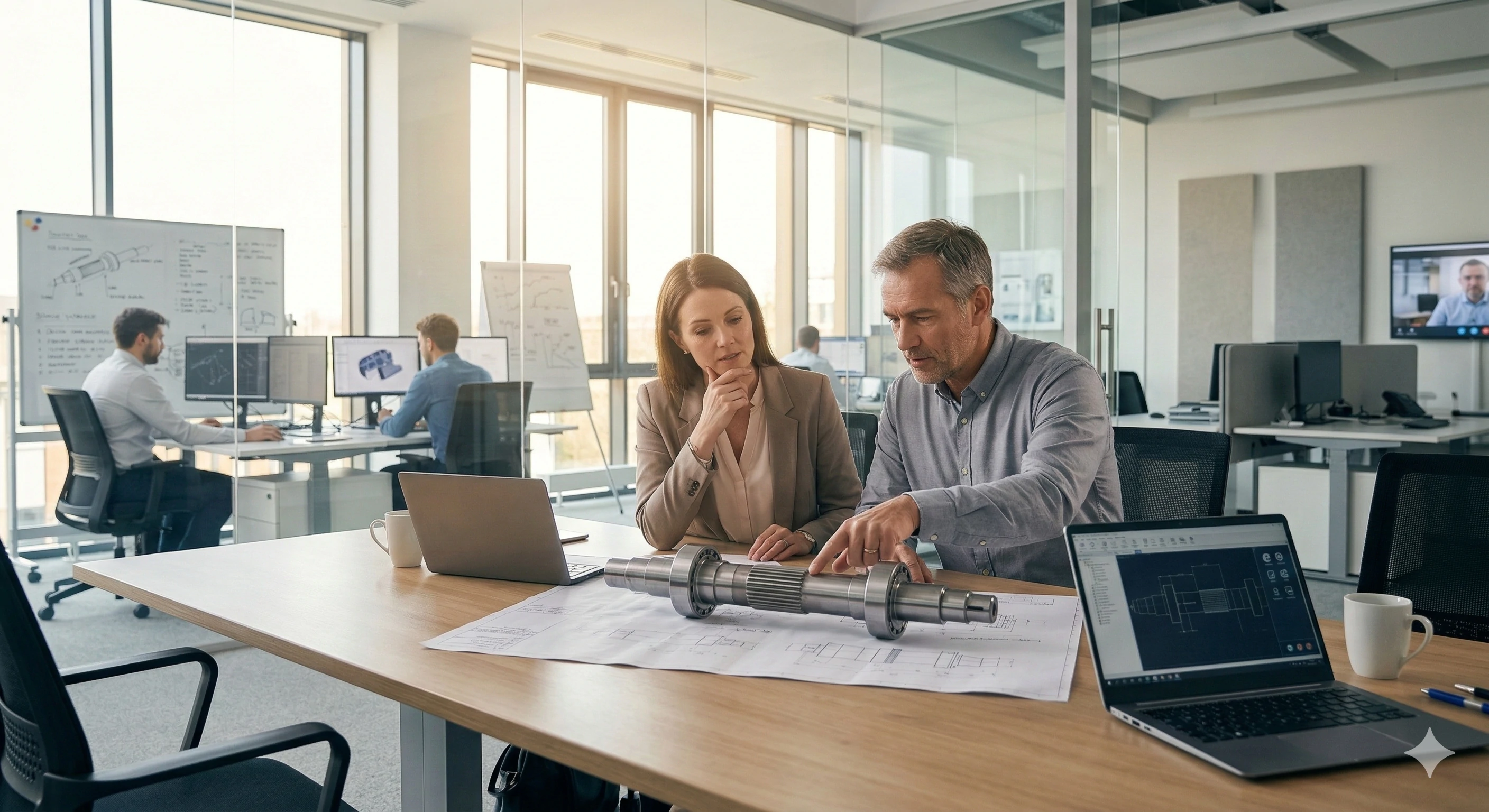
Why Do OEMs Partner With Custom Machining Facilities?
Relying on multiple vendors for turning, milling, and grinding often leads to mismatched tolerances and assembly headaches. We understand the frustration of piecing together inconsistent components. By partnering with a comprehensive machining facility, you receive fully finished parts ready for immediate assembly.
OEMs partner with custom machining facilities to access turnkey solutions that handle turning, milling, and finishing under one roof. This consolidated approach ensures strict dimensional control, exact custom thread pitches, and perfect bearing fits for reliable equipment assembly.
The Problem with Off-the-Shelf Components
Many companies try to save time by purchasing standard components. The problem with "off-the-shelf" parts is that standard rotary stock is only fine for a hobbyist. OEM machinery requires proprietary lengths, custom thread pitches, and specific alloy certifications. Standard parts cannot meet these strict engineering demands, leading to poor performance and premature wear.
The Turnkey Manufacturing Advantage
The turnkey solution is sourcing custom parts from a facility that handles the turning, milling, and finishing under one roof. This ensures strict dimensional control throughout the entire process. When we control every step, we guarantee the final quality. As a result, when you assemble your equipment, the bearing simply glides on perfectly every single time. We manufacture complex rotary components for the pump, agricultural, and industrial sectors.
Conclusion
A machine is only as reliable as the shaft that drives it. By combining advanced CNC turning, strict material selection, and rigorous runout testing, you guarantee the longevity of your equipment. Do your OEM machines require high-precision, low-runout custom shafts? We manufacture complex rotary components for the pump, agricultural, and industrial sectors. Send your technical drawings to our engineering team for a CNC machining quote.
Footnotes
1. Learn more about the various types of mechanical hardware and their industrial uses.
2. Explore the foundational engineering principles used in standard machinery design.
3. Read about the capabilities and history of modern automated machining centers.
4. Understand how precise engineering tolerances ensure parts fit correctly every time.
5. Discover the role of impellers in centrifugal pumps and industrial fluid dynamics.
6. See how ongoing material fatigue ultimately leads to stress fractures in metals.
7. Learn the fundamentals of the CNC machining process and industrial automation.
8. Explore the mechanisms and history of the lathe in manufacturing.
9. Understand the metallurgical science behind induction hardening for steel components.
10. Guide to how mechanical seals prevent fluid leaks in industrial pumps.