When we analyze pump failures in our facility or consult with clients about , the conversation almost always turns to the impeller. Many businesses struggle with pumps that lack efficiency or wear out prematurely because the internal components aren't matched to the specific fluid being moved. We have seen firsthand how a misunderstanding of this single component can lead to costly downtime and increased energy consumption. By understanding the specific mechanics of how this "heart" of the pump operates, you can make smarter procurement decisions for your machinery.
An impeller is a rotating component equipped with vanes or blades used to increase the pressure and flow of a fluid. Functioning as the heart of a centrifugal pump, it transfers energy from the motor to the liquid, accelerating it outwards to move water, oil, or chemicals efficiently through a system.
To understand why this component is so critical, we need to look beyond the basic definition. It is the bridge between mechanical energy and fluid motion.
How Does an Impeller Work (The Physics)?
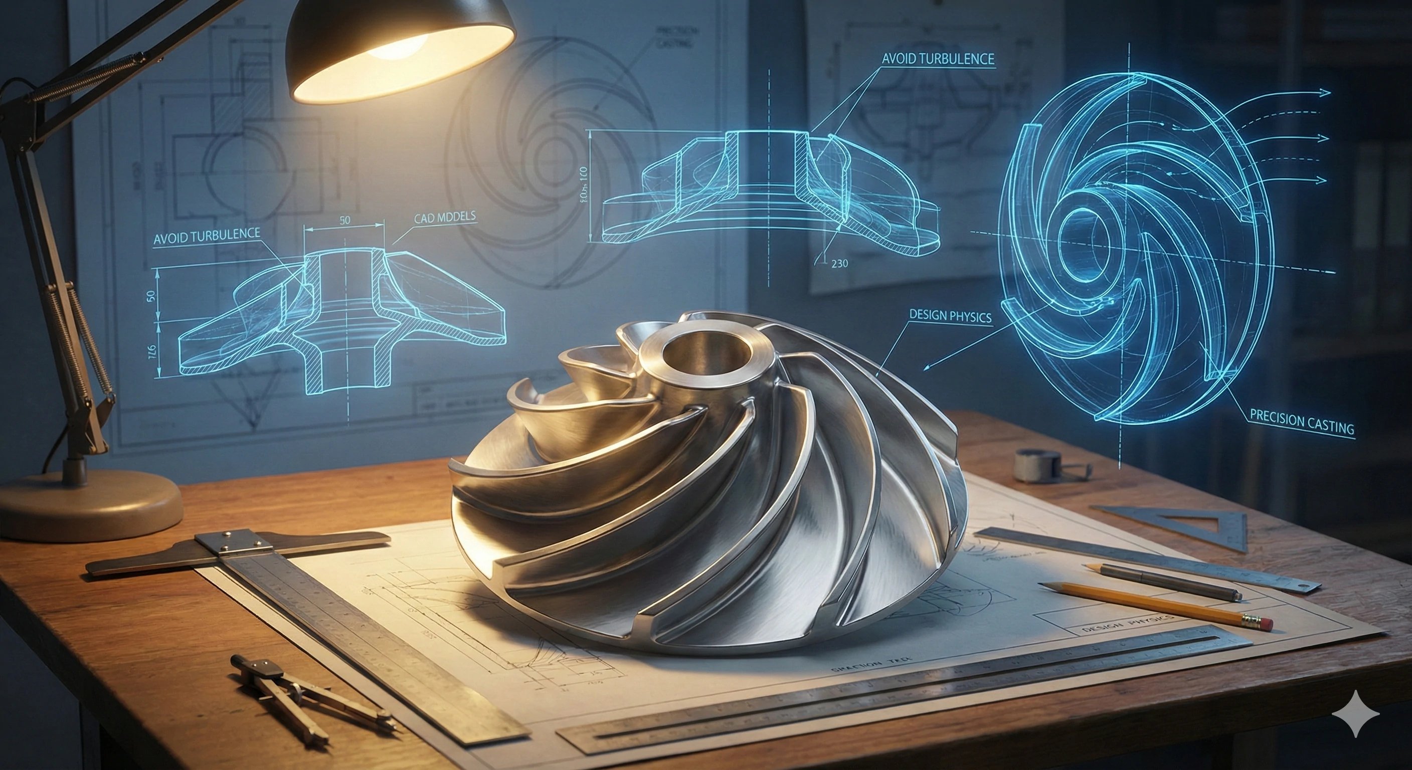
When our engineering team designs a new casting mold, we have to account for the precise physics of how the finished part will interact with fluids. We calculate the rotational forces and the stress points on the metal to ensure long-term durability. If the physics aren't aligned with the design, the pump will suffer from vibration and poor performance.
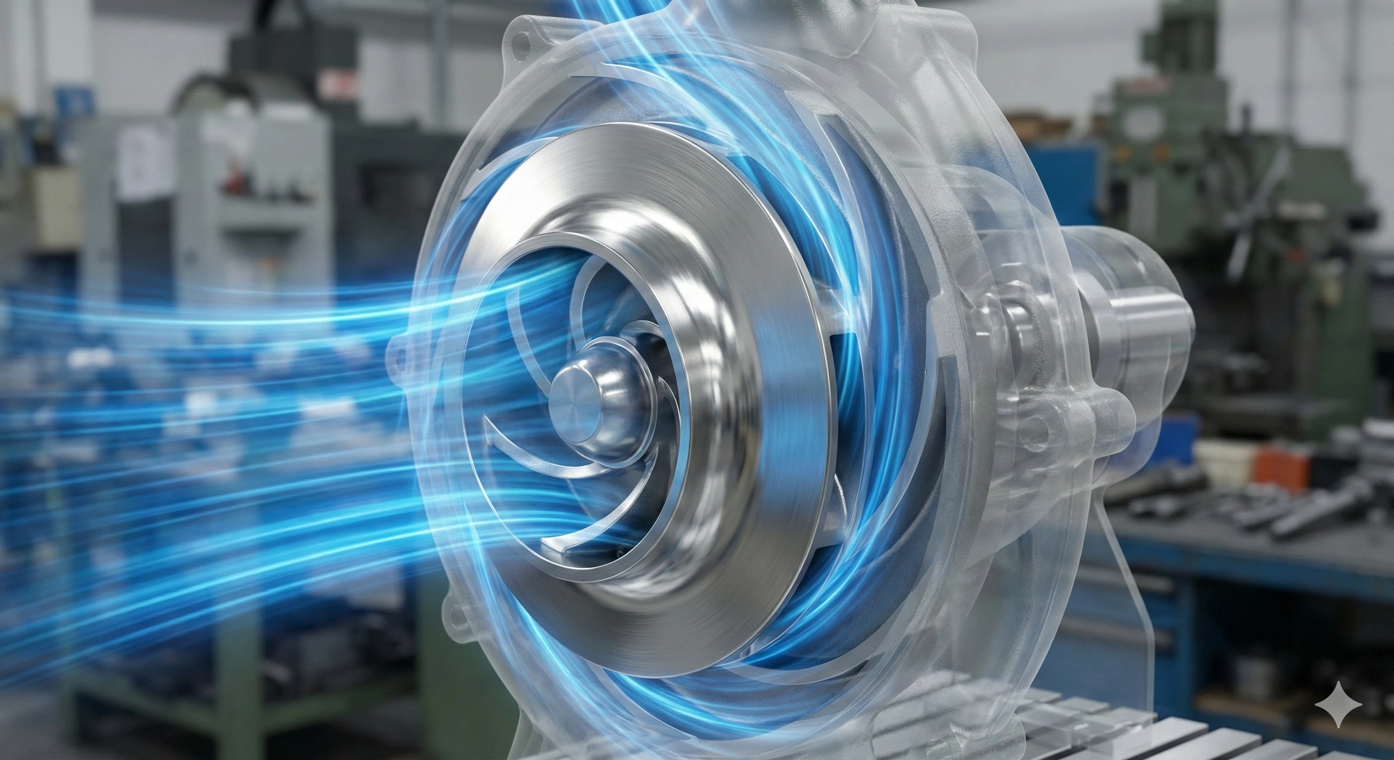
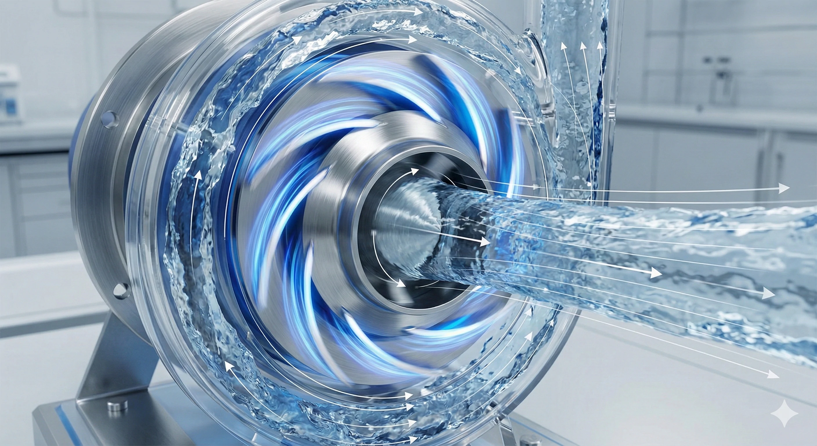
The impeller works by using centrifugal force to transfer kinetic energy from the motor to the fluid. As the component spins, it pushes the liquid away from the center of rotation, increasing its velocity and pressure, which discharges the fluid efficiently out of the pump outlet.
The physics behind an impeller is a fascinating study in energy conversion. When a motor drives the shaft, the impeller spins at high speeds. This rotation creates a low-pressure area at the eye (center) of the impeller, which draws the fluid in. Once the fluid enters the vanes, it is trapped and spun around.
Here, the principle of takes over. Just as you feel pulled outward when riding a spinning merry-go-round, the fluid is forced outward toward the edges of the impeller. This movement imparts kinetic energy to the fluid. As the fluid exits the tips of the vanes, this kinetic energy is converted into pressure energy by the .
The geometry is incredibly complex. The blades are rarely straight; they are curved backward or forward in 3D space to optimize the flow path and reduce turbulence. In our casting process, getting these curves perfect is essential. If the curve is off by even a fraction of a millimeter, it can cause hydraulic losses or cavitation, where bubbles form and implode against the metal. This physical interaction is why precision manufacturing is non-negotiable for high-efficiency pumps.
Key Physical Forces at Play
| Force Type | Function | Result |
|---|---|---|
| Centrifugal Force | Pushes fluid outward from the center. | Generates velocity and flow. |
| Kinetic Energy | Energy of motion transferred from the motor. | Increases fluid speed. |
| Pressure Energy | Conversion of speed as fluid hits the casing. | Allows fluid to travel through pipes. |
Impeller vs. Propeller: What’s the Difference?
We often receive inquiries where the terms "impeller" and "propeller" are used interchangeably, but in the world of , they perform opposite tasks. Clarifying this distinction is one of the first things we do during a technical consultation to ensure we are manufacturing the correct part for the client's application.
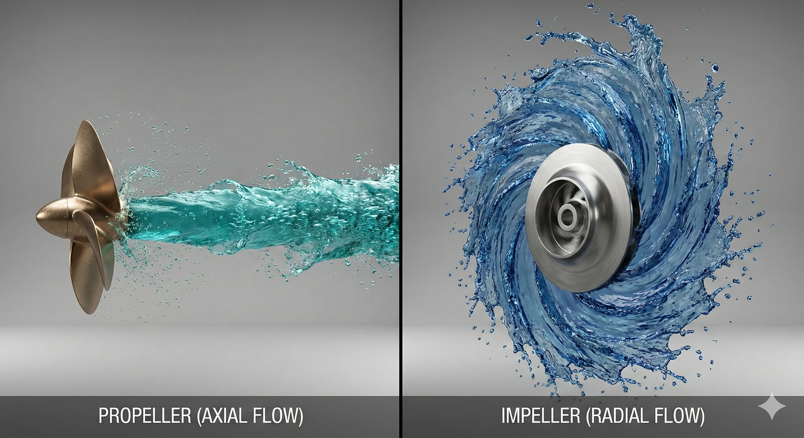
A propeller pushes fluid parallel to the shaft to create thrust for propulsion, while an impeller moves fluid perpendicular to the shaft to create pressure. Impellers are used in pumps to move liquids, whereas propellers are used on boats or planes to move the vehicle itself.
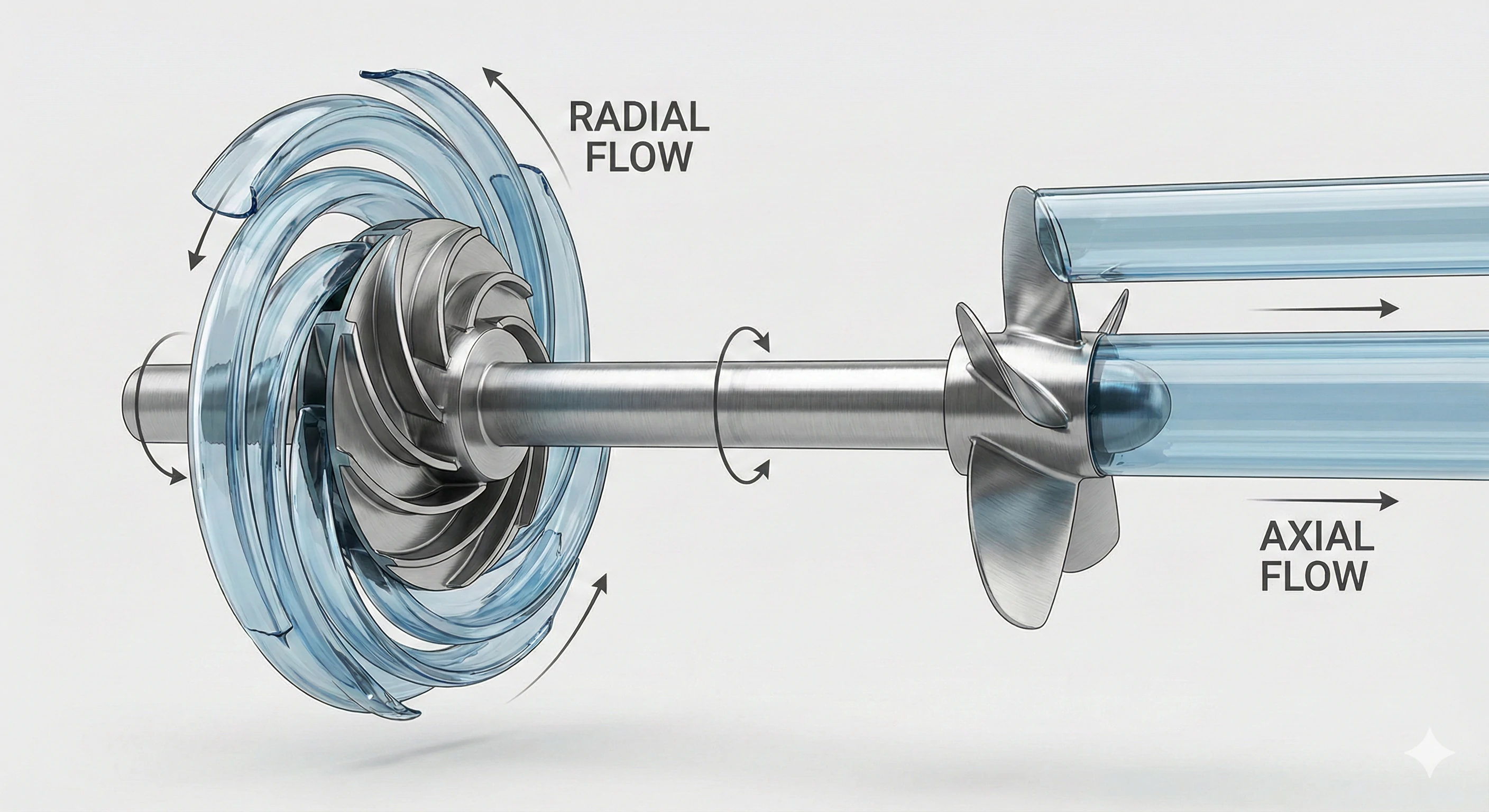
The confusion stems from the fact that both components look somewhat similar—they both have a central hub with blades radiating outward. However, the difference lies in the direction of the flow they create. A propeller creates Axial Flow. Imagine a household fan or a boat screw; it pushes air or water directly forward or backward, parallel to the shaft it spins on. The goal is usually or ventilation.
In contrast, the vast majority of impellers we cast are designed for Radial Flow. They take fluid in from the center ( ) and throw it outwards at a 90-degree angle to the shaft. This radial movement is what generates the high pressure needed to push water up a tall building or through a long pipeline.
There are hybrid designs, such as mixed-flow impellers, but the rule of thumb is simple: if you need to move a vehicle through a fluid, you use a propeller. If you need to move a fluid through a pipe, you use an impeller. Understanding this distinction helps in selecting the right pump curve and motor size. From a manufacturing standpoint, propellers are often simpler to cast because the blades are more open, whereas impellers often require complex internal coring.
Comparison of Motion
| Feature | Impeller | Propeller |
|---|---|---|
| Flow Direction | Perpendicular (Radial) to shaft. | Parallel (Axial) to shaft. |
| Primary Goal | Create pressure to move fluid. | Create thrust to move a vehicle. |
| Typical Use | Centrifugal pumps. | Boats, aircraft, fans. |
The 3 Main Types of Impellers (Design & Application)?
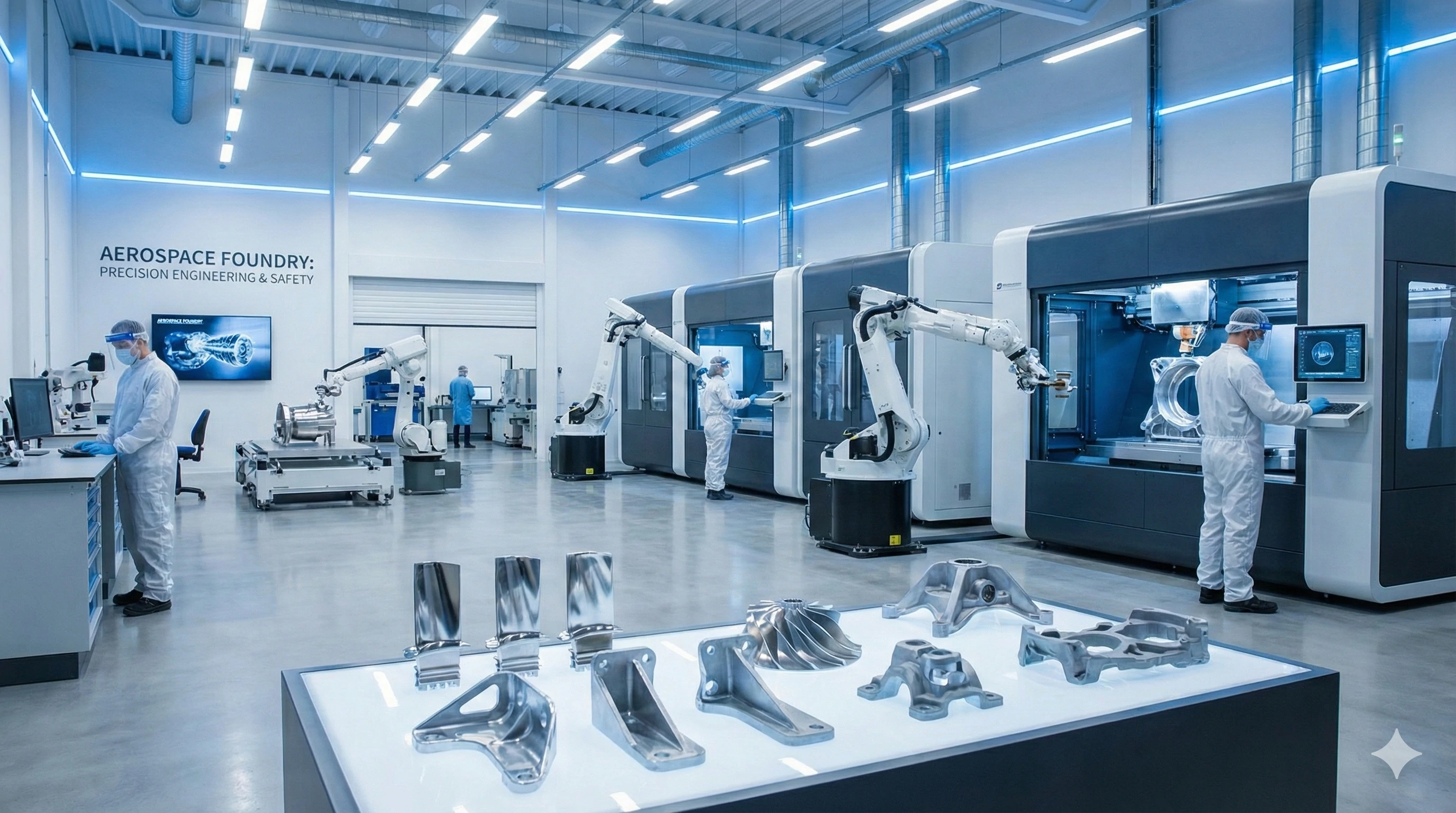
In our foundry, we do not believe in a "one size fits all" approach to casting. Different fluids require radically different blade configurations. We usually categorize these into three distinct designs, each serving a specific purpose depending on how clean or dirty the fluid is.
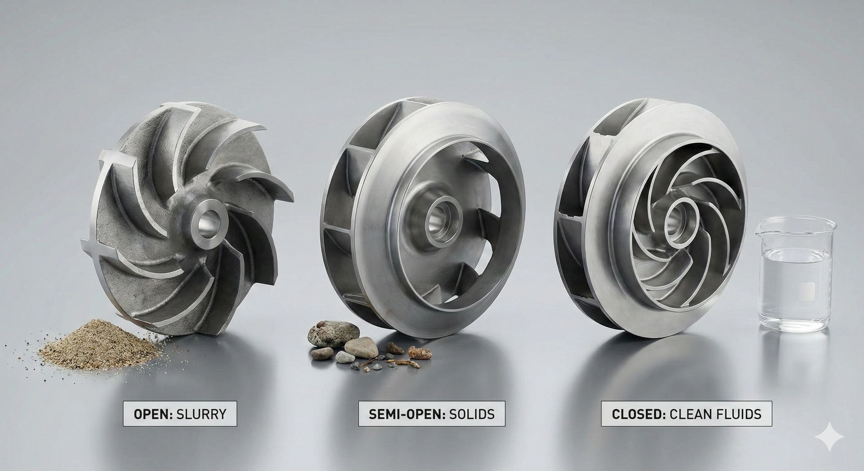
The three main types are Open, Semi-Open, and Closed impellers. Open types are best for handling solids and sludge without clogging, Semi-Open types offer a balance, and Closed types provide maximum efficiency for clean water but are the most difficult to manufacture.
Selecting the right type is a trade-off between efficiency and reliability. Here is a deeper look at how we distinguish them during the production planning phase:
1. Open Impellers
These are structurally the simplest. The vanes are attached to a central hub, but there is no wall (shroud) on either the front or the back. Because the vanes are exposed, these are excellent for "dirty" applications. If you are pumping sewage, sandy water, or , an open impeller is less likely to clog. However, they are generally less efficient because fluid can slip back around the edges of the vanes.
2. Semi-Open Impellers
This design features a back wall (shroud) that adds strength to the vanes, but the front remains open. We often cast these for industrial applications where the fluid might contain a small amount of debris, but reasonable efficiency is still required. They rely on a tight clearance between the vanes and the pump housing to maintain pressure.
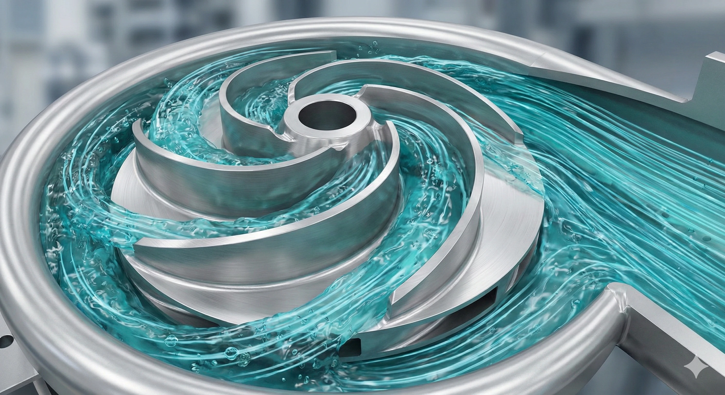
3. Closed Impellers
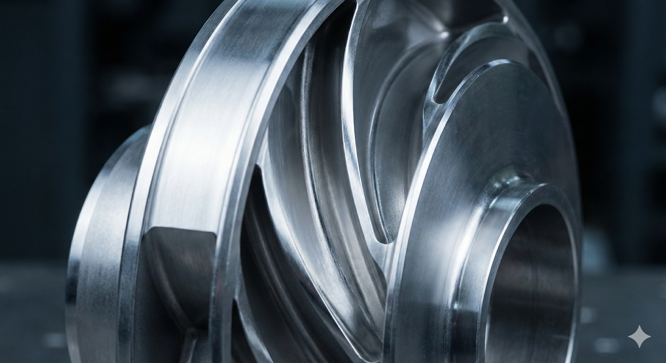
This is the gold standard for high-efficiency clean water pumps. The vanes are sandwiched between two discs—a front shroud and a back shroud. This creates enclosed channels for the water to flow through. While this maximizes hydraulic efficiency, it presents a significant manufacturing challenge. You cannot machine a closed impeller from a solid block easily because you cannot reach the internal channels. This is why Investment Casting (Lost Wax) is the only viable method to produce them accurately. We create a wax model of the internal channels, coat it in ceramic, and then melt the wax out to pour the steel.
Selection Guide
| Type | Best Application | Efficiency | Clog Resistance |
|---|---|---|---|
| Open | Sludge, sewage, high solids. | Low | High |
| Semi-Open | Industrial process water, trash pumps. | Medium | Medium |
| Closed | Clean water, HVAC, high pressure. | High | Low |
Material Selection: Why Stainless Steel?
We constantly test materials for durability because a failed pump component can shut down an entire factory line. While cast iron is cheap, we find it unsuitable for modern, demanding environments. Our production data shows that stainless steel offers the necessary longevity for critical applications.
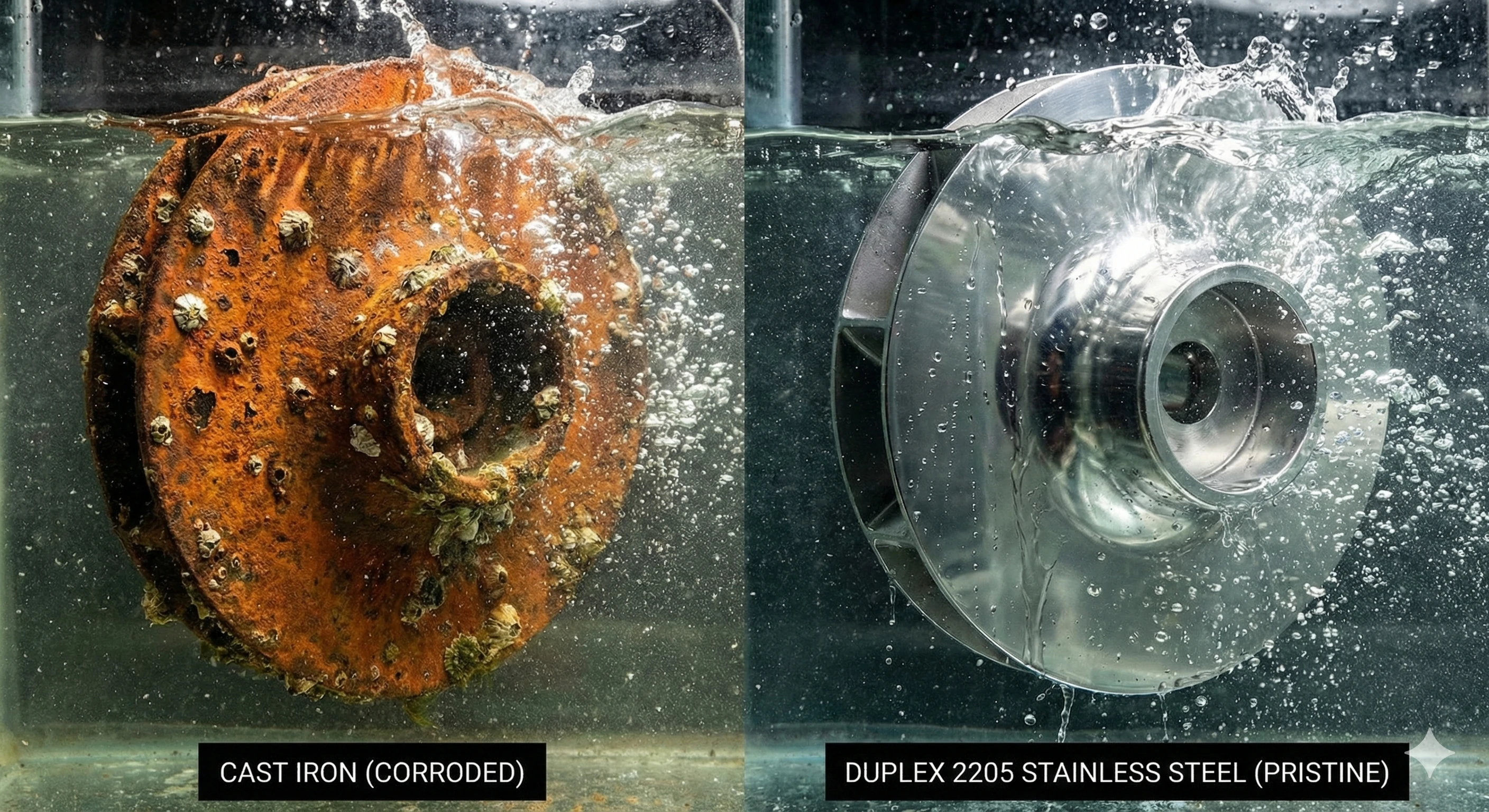
Stainless steel is the preferred material because it offers superior resistance to corrosion and cavitation compared to cast iron or plastic. Grades like 304, 316, and Duplex 2205 are essential for pumps handling salt water, chemicals, or high-speed fluids that would destroy lesser metals.
When an impeller spins at 3,000 RPM, it is subjected to intense physical and chemical stress. If the fluid is acidic or saline (like seawater), standard cast iron will rust and degrade rapidly. Once the vanes corrode, the pump loses balance, causing vibration that destroys the bearings and seals.
This is why we focus on Stainless Steel 304 and 316. These alloys contain , creating a passive layer that prevents rust. For even more extreme environments, such as desalination plants or chemical processing, we utilize Duplex 2205.
is incredibly resistant to a phenomenon called Cavitation. Cavitation occurs when pressure drops rapidly inside the pump, creating vapor bubbles. When these bubbles move to a high-pressure area, they implode with tremendous force, blasting small pits into the metal surface. Over time, this looks like the metal has been eaten away. Duplex 2205 has a microstructure that resists this pitting much better than standard steel. By choosing the right alloy during the casting process, we extend the lifespan of the pump significantly, reducing the total cost of ownership for the user.
Manufacturing: Why Investment Casting is Essential for Impellers?
In our experience fulfilling orders for global OEMs, we have found that traditional machining methods simply cannot compete with casting for these components. When we receive a complex CAD drawing for a closed impeller, we know immediately that milling it from a solid block would be wasteful and prohibitively expensive.
Investment casting is essential because it allows for the production of complex, 3D curved geometries and internal channels that are impossible to machine. This process yields a near-net-shape part with superior balance and surface finish, drastically reducing waste and manufacturing costs.
The geometry of a high-performance impeller involves compound curves. The blades twist and turn in ways that a CNC tool cannot easily follow, especially when those blades are shrouded (closed). If you tried to machine this from a solid block of stainless steel, you would end up turning 70% of that expensive material into scrap chips.
At our foundry, we utilize the Investment Casting (Lost Wax) process. Here is why it is superior for this specific application:
-
Internal Channels: We inject wax into a mold to create the exact shape of the water passages. We then coat this wax tree in . Once the ceramic hardens, we melt the wax out, leaving a perfect hollow cavity. This allows us to create the complex internal voids of a closed impeller that no drill bit could ever reach.
-
Surface Finish: Pump efficiency relies on low friction. A rough surface creates drag. Investment casting produces a very smooth surface finish (typically 125 RMS or better) right out of the mold. Sand casting, by comparison, leaves a rough, grainy texture that creates hydraulic drag.
-
Balance: Because the mold is precise, the resulting cast part is naturally balanced. This reduces the amount of post-production grinding and balancing required, ensuring the pump runs quietly and smoothly.
Conclusion
The impeller is far more than just a spinning fan; it is a marvel of engineering that dictates the efficiency and reliability of your entire fluid system. From the physics of centrifugal force to the material science of Duplex stainless steel, every detail matters. Whether you require an open design for slurry or a precision-cast closed impeller for high-pressure water, the manufacturing quality is the deciding factor in performance.
If you are looking for a supplier who understands the intricacies of casting complex geometries, we are here to help. We specialize in OEM Investment Casting and can turn your CAD drawings into high-performance stainless steel parts.
Need custom stainless steel impellers for your pump or machinery business? Send us your CAD drawings for a quote today.
Footnotes
1. Comprehensive overview of fluid dynamics principles and applications.
2. Physics explanation of centrifugal force in rotating systems.
3. Detailed guide to pump volute types and functions.
4. Introduction to the study of fluids in motion.
5. NASA guide on how propulsion systems generate thrust.
6. Engineering principles regarding suction pressure in pump systems.
7. Definition and characteristics of slurry mixtures in industry.
8. Role of alloying elements in preventing steel corrosion.
9. Technical benefits and applications of Duplex stainless steels.